Downloads for hobby purposes. Downloads für Hobby-Zwecke.
Hinweis auf Cookies: T-Online erhebt bei Nutzung dieser Webseiten technische Daten des Nutzers (siehe Datenschutzerklärung auf der Startseite). Wenn Sie diese Seiten weiterhin nutzen, erklären Sie sich damit einverstanden. Wenn Sie nicht einverstanden sind, beenden Sie bitte die Nutzung dieser Webseite.
Themen auf dieser Seite: Main topics on this page:
-HF-Suchkopf: Berührungslos HF-Signale erfassen (für Oszilloskop und Frequenzzähler) HF probe. How to grasp HF signals without contact (for oscillograph and frequency counter
- Strombegrenzer: So schützen Sie Ihr Gerät vor Überstrom und Kurzschluss Current limiter: How to protect your device from overload and short-circuit
- Warum zeigt meine Funkuhr immer die falsche Uhrzeit? DCF77-Empfänger: Für die Vermeidung von Funkstörungen und die erfolgreiche Suche nach dem besten Aufstellort des Funkweckers Why is my radio controlled clock going wrong? Why doesn't it have the right time? Receiver for time signal transmitter DCF77: This device will help you with the avoidance of radio interference and the successful discovery of the best place for your radio controlled clock
- Wasser-Alarm This device will give a warning of unwanted water floods
- Steckernetzteil ohne Funkstörungen für 3 Volt = Plug-in Mains Adaptor without Radio Interference for 3 Volt DC Output
- Mini-Whip-Antenne angelehnt an die Konstruktion von PA0RDT: Weichen Sie den Funkstörungen durch eine Außenantenne aus und verbessern Sie den Empfang Mini Whip Antenna after the Construction of pa0rdt: Evade radio interference by use of an external antenna and improve radio reception
- Oscillator for 3276800 Hz (=3276.8 kHz =3.2768 MHz) Oszillator für 3276800 Hz (=3276,8 kHz = 3,2768 MHz)
- Free running HF-oscillator for measurement purposes freilaufender HF-Oszillator für Messzwecke
- Linear power adaptor for your laptop (without radio interference, if you want to decode Shortwave Radiogram) Lineares Netzteil für den Laptop (ohne Funkstörungen)
- Adaptor for the soundcard (in between radio and computer) Adapter für den Anschluss des Radios an die Soundkarte des Computers
- 13560 kHz AM transmitter (very low power) Kleinstleistungs-Sender für 13560 kHz und Amplitudenmodulation
- medium wave AM audion transistor radio receiver Mittelwellen-Audion
- shortwave AM audion transistor radio receiver "Trabant KM" Kurzwellen-Audion "Trabant KM"
- Sharp Pocket Computer PC-1401 or PC-1403: Parallel Printer-Interface (Centronics)
Security advice Sicherheits-Hinweis
If you are going to use these informations, please take care of your health and prevent yourself from electrical shock and other health hazards. All instructions published here are checked but the webmaster and author cannot accept responsibility for any damage, loss or injury; you as a user of this information act on your own responsibility. Related knowledge and skills are expressly assumed, and they will not be imparted. Please read the "caution!" note at the bottom of this particular website.
If I publish plans, schematics, images or descriptions of electric and electronic devices here, I by no way intend to claim that anything complies with security rules, laws and/or other regulations. Standards, regulations, and so on may vary from country to country and from time to time, and it is obligatory to you to check by yourself if what you do is in compliance with appropriate standards and laws.
Constructing electronics, working with mains voltage and soldering is not suitable for children any way. Young people will need supervision and instruction by adults with appropriate knowledge. Whoever uses the information of this web pages is responsible by himself for any possible consequences.
Wenn Sie die Informationen dieser Webseite(n) nutzen, so achten Sie bitte darauf, dass Sie Ihre eigene Gesundheit bewahren, und schützen sich vor elektrischem Schlag und anderen gesundheitlichen Gefahren. Alle Anleitungen, die hier veröffentlicht sind, wurden geprüft, aber der Webmaster und Autor lehnen die Verantwortung für jeglichen Schaden, Verlust oder körperliche Schädigung ab; Sie als Nutzer dieser Information handeln auf eigene Verantwortung. Entsprechende Kenntnisse und Fähigkeiten werden ausdrücklich vorausgesetzt und hier nicht vermittelt! Bitte lesen Sie die "Achtung!" -Notiz ganz unten auf dieser Webseite. Indem ich hier Pläne, Schaltpläne, Bilder oder Beschreibungen von elektrischen oder elektronischen Baugruppen/Geräten veröffentliche, behaupte ich weder direkt noch indirekt, dass irgendetwas davon mit Sicherheitsregeln, Gesetzen und/oder anderen Vorschriften in Einklang steht. Standards, Regeln usw. können von Land zu Land unterschiedlich sein und sich über die Zeit ändern, und es ist für Sie obligatorisch, selber zu klären, ob das, was Sie tun in Übereinstimmung mit einschlägigen Standards und Gesetzen erfolgt.
Der Bau von Elektronik, der Umgang mit Netzspannung sowie Löten sind für Kinder völlig ungeeignet. Jugendliche benötigen Aufsicht und Anleitung durch entsprechend ausgebildete Erwachsene. Wer die Informationen dieser Webseiten nutzt, trägt selber die Verantwortung für die möglichen Konsequenzen.
Recycling of electronic material Wiederverwendung von elektronischen Bauteilen
You may find that some of the electronic parts I use here, are outdated or at least NOS (new old stock). Please don't worry about that. First, I like to recycle electronic parts, just because I would feel sorry about throwing them away if they are still working well. Second, electronic waste may alter the environment, so recycling is a little bit of environmental protection. Third, if electronic parts are of old age that does not mean on principle that they will not work properly. Often, it's just the other way round: If parts have shown that they withstood the years, then sometimes they may be of higher quality than those you just now purchased from new stock.
Einige der hier verwendeten elektronischen Bauteile mögen veraltet aussehen, oder wie NOS (new old stock = unbenutzte alte Lagerbestände). Lassen Sie sich davon bitte nicht irritieren. Erstens verwende ich gerne ausgeschlachtete "recycelte" elektronische Bauteile, weil es schade darum wäre, sie zu vernichten, wenn sie noch gut funktionieren. Zweitens schädigt Elektronikschrott die Umwelt, daher ist Recycling von Bauteilen ein kleiner Beitrag zum Umweltschutz. Drittens: Alte Bauteile müssen nicht zwingend schlecht funktionieren, nur weil sie alt sind. Im Gegenteil: Sie haben über die Jahre ihre Standfestigkeit bewiesen, und deswegen kann es sogar manchmal sein, dass die Qualität der alten Bauteile höher ist als diejenige aus neuer Produktion.
======================================
Please think about before you do your experiments: (1) Nothing is as easy as it looks. (2) Everything takes longer than you think. (3) If anything can go wrong, it will. (Murphys's laws)
Zuerst die Beobachtungen und der Versuch, dann das Denken ohne Autorität, die Prüfung ohne Vorurteil. (Rudolf Virchow)
======================================
HF-Suchkopf HF probe Das von einem Oszillator, beispielsweise einem frei schwingenden Oszillator und dessen Schwingkreis gelieferte Signal zu untersuchen, erfordert die Verwendung des Oszilloskops oder Frequenzzählers. Diese Geräte werden typischerweise über Testklemmen und ein abgeschirmtes Anschlusskabel an den Oszillator angeschlossen. Dies führt unvermeidlich zu unerwünschten Frequenzveränderungen oder sogar Abbruch der Schwingungen.
In order to investigate into the signal that is produced by an oscillator, e.g. by a free running oscillator, you will use an oscillograph or a frequency counter. Both will be connected to the oscillator by use of test probes wich will do the connection via a shielded cable. Unfortunately, this will inevitably lead to frequency offset or even stopping of oscillation.
Der HF-Suchkopf dient der berührungslosen Erfassung von HF durch Annäherung der Spule des Suchkopfes an Spulen, Drosseln, Antennen, Leitungsbahnen oder Schwingkreise, die HF führen. Der HF-Kopf empfängt in erster Linie induktiv, ist aber innerhalb gewisser Grenzen auch in der Lage, rein kapazitiv in die Suchspule eingestreute HF zu erfassen. Der von HF-Suchkopf erfolgreich erfasste Frequenzbereich ist 300 kHz bis 30 MHz.
This HF probe is made for collecting HF just by bringing the coil of the probe near to coils, choking coils, antennas, conductors or resonant circuits which contain HF. The HF probe receives mainly by induction but is also apt to collect HF which is scattered into the probe by capacity. Frequency range ist from 300 kHz up to 30 MHz.
Als Gehäuse empfiehlt sich ein schmales Röhrchen aus Kunststoff, in welches die kleine Platine eingefügt wird. Das Röhrchen trägt auf der Außenseite die Suchspule.
A small plastic tube is used as casing. The printboard is mounted inside of the tube. On the front end of the tube we place the coil of the probe.
Für die Platine wurde eine Punkt-Lochraster-Platine verwendet.
The printed board ist made of custom made punctured Pertinax.
Die Spule ist links angelötet, die Kabel zum Oszilloskop bzw. Frequenzzähler und die Leitung für die Stromversorgung sind rechts zu erkennen.
On the left, the coil is soldered. The shielded cable to the oscilloscope or frequency counter is on the right side, as well as the wire for power supply.
Die Bauteile sind - dem Signalverlauf entsprechend - auf der Platine von links nach rechts angeordnet. Der Ausgang der Schaltung mit dem Collector des zweiten Transistors rechts ist möglichst weit entfernt vom Eingang der Schaltung links.
Electronic parts are mounted from the left to the right following the path of the signal. Signal output to right end of the printed board is separated from the signal input as far as possible.
Die Platine wird in das Plastik-Röhrchen geschoben, die Spule angeschlossen und das Ganze mit Schrumpf- schlauch umkleidet.
The printed board is placed inside of the small plastic tube. The coil is soldered to the signal input of the printed board. Finally, a black shrinking plastic hose is placed over everything.
Noch aus einigen Zentimetern Abstand ist ein stabiles Signal zu empfangen.
Even from a distance of several centimeters, a stable signal is received.
Stabile Anzeige des Frequenzzählers (17,735 MHz).
Stable display of the frequency counter (17.735 MHz).
======================================
Strombegrenzer:So schützen Sie ihr Gerät vor Überstrom und Kurzschluss
Current Limiter: How to protect your device from overload and short-circuit
Mit der nachfolgenden Schaltung begrenzen Sie den Gleichstrom auf einen Wert um 5 Ampere und schützen die Stromquelle zugleich vor Kurzschluss. Das Besondere an dieser Schaltung ist der Kipp-Effekt: Wird ein Strom von 5 A überschritten, schaltet die Überstromsicherung vollständig ab. Sie muss erst über den Taster reaktiviert werden - oder die Last muss kurzzeitig vollständig abgeklemmt werden, um den Stromfluss erneut zu starten.
The following electronic circuit will limit the direct current to an amount of 5 Ampere. Furthermore, the current source is protected from short-circuit. The speciality of this circuit is the tilting behaviour: If the current exceeds 5 A the circuit will turn off completely. It stays in the "off" position and will not reactivate until you press the button, or until you remove the load for a short time.
Schematics
Principle by Georg Niepel, choice of transistor types and experimental setting of resistor dimensions by Volker (Trient, Italy) Schematics drawing by Georg Niepel (author)
Diese Schaltung ist ein schönes Beispiel für gelungene Zusammenarbeit über das Forum "Dampfradioforum". Die Schaltung war eine Schreibtischentwicklung von Georg Niepel, Autor dieser Webseite, die Wahl der Transistortypen und die Dimensionierung der Widerstände erfolgten per Experiment durch Volker (Trient, Italien).
This circuit is a perfect example of cooperation via "Dampfradioforum". Originally, the circuit was a "desktop development" by Georg Niepel (author of this web site), but choice of transistor types and finding of correct resistor values were done experimentally by and in cooperation with Volker (Trient, Italy).
The board as designed by Volker (foto courtesy of Volker, Trient, Italy)
Funktion der Schaltung: T1 schaltet den Strom ein und aus. Im eingeschalteten Zustand fließt der Strom vom Eingang (+) auf der linken Seite des Schaltbildes zum Ausgang (+) auf der rechten Seite; dort ist die Last angeschlossen. Der Transistor schaltet ein, sobald die Basis über den Widerstand 47 Ohm mit Masse verbunden ist.
Dies lässt sich forciert erreichen, indem man die Taste drückt. Sofort schaltet der T1 durch. Er bleibt allerdings auch durchgeschaltet, wenn und solange T4 leitend ist. T4 wird mit Hilfe des Basis-Widerstands (2k2) angesteuert und ist solange durchgesteuert, wie T3 sperrt. Die Basis von T3 ist über den Widerstand 1k mit dem Emitter verbunden und sperrt solange, bis über den 2k7 von T2 her ein positives Potential zur Basis des T3 geleitet wird. Dies geschieht dann, wenn T2 durchschaltet. T2 schaltet nur dann durch, wenn zwischen Basis und Emitter des T2 eine Spannung von über 0.5 Volt anliegt. Dies ist einerseits dann der Fall, wenn der Strom durch den T1 so groß wird, dass entsprechend hohe Spannung über dem Widerstand 0.1R abfällt. Dieser Widerstand sowie die Potentiometer-Einstellung bestimmen, bei welchem Strom der T2 schaltet. Die gezeigte Dimensionierung bewirkt ein Schalten bei 5 Ampere oder darüber. Andererseits schaltet T2 auch dann durch, wenn die Spannung zwischen Basis und Emitter von T2 deswegen größer 0.5 Volt ist, weil T1 sperrt. Dies ist immer dann der Fall, wenn T2 wegen Überstrom angesprochen hat: T2 bringt T3 zum Leiten, dies sperrt T4, und das wiederum führt zum Sperren von T1. Dieser blockierte Zustand bleibt so lange bestehen, bis entweder die Last kurz abgeklemmt wurde oder die Taste gedrückt wurde.
Function of circuit: T1 is designed to switch the current on and off. In the "on" position, the current goes from the input (+) which you see to the left of the schematics to the output (+) which is situated to the right; there the load is connected. The transistor T1 will switch on, if and when its Basis lead is connected to ground via the resistor 47 Ohms.
You may force the T1 to the "on" state by pressing the button. Immediately T1 will switch "on" so the current goes through it. T1 will also be kept in the "on" state if and as long as T4 is conducting. By the Basis resistor 2k2, T4 is driven to the conducting state. T4 is kept in the conducting state as long as T3 is locked. T3 is kept in the locked state by the resisitor 1k which keeps the Basis of T3 to ground potential. The transistor T2 is controlling T3. From the moment when a positive voltage is coming from T2 via the 2k7 resistor to the Basis lead of the T3, T3 will conduct, T4 will lock and T1 will switch to the "off", thus stopping the current flow from (+) Input to (+) Output.
T2 will conduct only if a voltage of above 0.5 Volts is headed for the Basis and Emitter leads of T2. On the one hand this is the case if current through T1 and resistor 0.1R is high enough due to overload or short circuit on the load side. The resistor and the trimming of the potentiometer are decisive which current will drive the T2 from locking to conducting state, thus triggering the circuit to tilt and stop the current flow. On the other hand, the voltage to Basis of T2 is high if T1 is locked in the "off" state. This will keep the circuit blocked after an overload happened. The current flow is blocked until either the button is pressed or the load is removed from the (+) output for a short time.
last update: 2020-11-09
=================================
DCF-Empfänger: Für die erfolgreiche Suche nach dem besten Aufstellort des Funkweckers Receiver for time signal transmitter DCF77. This device will help you to find the best place for your radio controlled clock
DCF-Symbol im Display eines Funkweckers DCF symbol as shown by the display of a radio controlled clock
Warum zeigt mein Funkwecker häufig die falsche Uhrzeit? Warum stellt sich meine Funkuhr nicht mehr automatisch auf die Sommerzeit um?Die Ursache liegt im mangelhaften Empfang des Zeitzeichensenders DCF77.
Why is my radio controlled clock going wrong? Why doesn't it switch to the right time automatically? In most cases, the clock fails through a lack of reception of the radio timer signal. In Germany, most radio controlled clocks are tuned to DCF77. In Great Britain it's a different one: MSF.
Funkstörungen werden immer intensiver. Sie werden verursacht durch Energiesparlampen, Schaltnetzteile, Fernsehgeräte usw, und sie stören auch Funkwecker bzw. Funkuhren. Diese Uhren empfangen das Zeitsignal des bei Frankfurt am Main gelegenen Senders DCF77. Dieser Sender arbeitet auf 77.5 kHz. Diese Frequenz liegt größenordnungsmäßig in den durch Schaltnetzteilen verseuchten Frequenzen.
Radio interference is getting stronger and stronger. It comes from energy saving bulbs, switch mode power supplies, TV sets and so on, and it hinders radio controlled clocks from working correctly. Those clocks receive the timing signals from the transmitter DCF77 which is sited near to Frankfurt am Main in Germany. The working frequency is 77.5 kHz. Or, if you are in Great Britain, radio controlled clocks depend on the transmitter called MSF. You can read elsewhere that it is located near Anthorn (Cumbria). The signal may be derived from an atomic clock which possibly stands in Teddington. The working frequency of MSF is 60.0 kHz. Switching mains supplies use frequencies in the frequency band around these frequencies, thus resulting in tremendous interference of function.
Empfänger zum Nachweis des DCF77 Signals. Ganz links: Antenne. Rechts: 9-Volt-Batterie. Receiver to detect the time signal DCF77. Far left: antenna. Right: 9-Volt battery
Der hier beschriebene Empfänger ist ein Zweikreis-Direktmisch-Empfänger. Er ermöglicht den Empfang des Zeitsignals und dient dabei der Suche sowohl nach Störquellen als auch nach dem optimalen Standort und der optimalen Antennenausrichtung des Funkweckers oder der Funkuhr. The DCF77-receiver described here uses the Homodyne Detection principle for the reception of the timing signal. We want to detect sources of intereference as well as we want to find the best place and orientation for our radio controlled clocks.
Schaltbild Empfänger für DCF77. Auf dem Download wesentlich besser zu sehen (siehe unten)! Please use the download for superior quality of graphic (below).
Das Schaltbild des DCF77 Empfängers können Sie downloaden. Bitte (doppel-)klicken Sie auf den Button oben.
You may download the schematics of the DCF77 time signal receiver. Please (double-) click on the button you see above.
Die Schaltung besteht aus den folgenden drei Baugruppen: (1) DCF77-Antenne (77.5 kHz) mit HF-Verstärker (2) lokaler Oszillator BFO mit 78.3 kHz (3) Demodulator und NF-Verstärker
The circuit consists of three constructive parts as follows: (1) ferrite antenna for the DCF77 signal on 77.5 kHz and RF amplifier (2) local oscillator (beat frequency oscillator BFO) on 78.3 kHz (3) demodulator and audio amplifier
Teil (1) DCF77 Ferrit-Antenne. Sie ist als Schwingkreis für 77.5 kHz geschaltet. Rechts unten erkennt man den zweiten Schwingkreis für 77.5 kHz. Part (1) The ferrite antenna is a resonant circuit for 77.5 kHz. On the lower right you see the second resonant circuit for 77.5 kHz.
Der Ferritstab ist 50 mm lang x 8 mm Durchmesser. Die Spule auf dem Ferritstab besteht schätzungsweise aus 110 Windungen in 3 Lagen. Die Kreiskapazität ist 6n8. The ferrite rod is 50 mm long x 8 mm diameter. The coil on it is of 110 turns in 3 layers. The capacitor is 6n8.
Ferritantenne und HF-Verstärker-platine. Rechts unten der zweite Schwingkreis. Darüber der Demodulator. Ferrite rod antenna and RF amplifier board. To the lower right: the second resonant circuit. Above: Demodulator board.
Teil (2) Schaltbild des BFO 78.3 kHz (lokaler Oszillator).
Part (2) BFO 78.3 kHz (local oscillator) schematics
Lokaler Oszillator (BFO) für 78.3 kHz
Teil (3) Demodulator und NF-Verstärker
Part (3) Demodulator and audio amplifier
Demodulator und NF-Verstärker. Die erste Stufe ist auf der oberen Platine (wieder- verwertetes Material), die zweite Stufe auf der unteren.
Demodulator and first stage of audio amplifier is on the upper board (recycling material), the second stage on the lower one
Die Beschreibung der Schaltung, des Aufbaus und der Anwendung finden Sie in dem Download. Bitte einfach das oben stehende Symbol anklicken.
The description of the circuit, the mounting and the usage is in German only, I'm sorry. If you want, you may download the text by click onto the symbol above.
But I'll try to give to you a short description. The german DCF77 is resembled by the british MSF (Teddington) on 60.0 kHz. Both give time signals by use of CW which means "continuous wave". Both are switching the power of the transmitter on and (nearly) off once every second. Wishing to "hear" this signal, one has to find a way to produce an audible sound from the DCF77 77.5 kHz (or MSF 60.0 kHz) signal which comes into the antenna. The way we are solving this task here, is to use a BFO (beat frequency oscillator) and a mixer. The BFO of our receiver is built to produce a constant signal of 78.3 kHz to match the DCF77 needs. If you want to hear the signal of MDF, then you should tune the BFO to 60.8 kHz. Within the mixer (demodulator), both signals are combined: the DCF77 signal coming from the antenna and the BFO signal. Or, if you will, the MDF signal coming from the antenna and the BFO signal. The resulting signal is the difference of both, hence 78.3 kHz - 77.5 kHz = 0.8 kHz or 800 Hz, as to speak of DCF77. With MDF, its 60.8 kHz - 60.0 kHz = 0.8 kHz or 800 Hz, too. This audio signal of 800 Hertz can be heard easily. It's a tone about one octavce above the concert pitch "a".
So what we hear is a tone going on and off one time per second. Now we can use our ferrite antenna as a direction finding equipment. You can turn it horizontally, and if you hear the tone as loud as possible, the broad side of the ferrite rod shows the general direction to the transmitter. Much more specific will be the minimum, it is rather sharp. With the antenna turned to the minimum of the tone, the tip of the ferrite rod points to the transmitter (or to the opposite side).
Die Empfängerschaltung enthält ganz bewusst keine automatische Verstärkungsregelung (automatic gain control, AGC). Infolgedessen sind Minima und Maxima ganz besonders genau zu orten.
The circuit of the receiver does not use automatic gain control (AGC). Therefore, the direction of every minimum and maximum appears particularly sharp.
Kaum zu glauben, aber wahr: Dieser DCF77-Funkwecker erzeugt selber Funkstörungen bei 77.5 kHz und behindert damit seine eigene Funktion. Ein Wunder, dass er überhaupt funktioniert.
Unbelievable, but true: This DCF77 radio controlled clock by itself produces radio interference on 77.5 kHz, hence hindering its own function. It surprises me that it is working nonetheless.
Now from the locating with our little receiver, you know which orientation of your radio controlled clock may give you the best signal strength of the timing signal. Using the directional antenna, you also may find out where local interference is minimum. There you may place your radio controlled clock. Sometimes, only a few inches will make a big difference. For example, extensive metal frames hidden behind the surface of light weighted walls or other long rod-shaped metal material just behind the wallpaper, may transmit local interference without being connected to anything. Even more, hidden electrical lines within the wall may transmit strong interference. If by chance you've placed your radio-controlled wall clock just there, you may be dissapointed about your clock going wrong. If you hang your wall clock just about a foot aside into a place where there is little or no interference, the problems are gone. And our little receiver can tell you where such place is.
Mit unserem kleinen Empfänger können Sie nun herausfinden, welche Position im Raum und in welche Himmelsrichtung gedreht Sie das Gehäuse der Uhr aufstellen müssen, um optimale Signalstärke und optimalen Empfang des Zeitzeichen-Signals zu erzielen. Mit der richtungsabhängigen Antenne können Sie auch herausfinden, an welchem Aufstellort die Funkstörungen am geringsten sind. Manchmal machen einige wenige Zentimeter einen großen Unterschied. Beispielsweise, wenn ausgedehnte Metallrahmen hinter Leichtbauwand-Oberflächen verlaufen, können diese massive Funkstörungen abstrahlen, ohne mit irgendetwas verbunden zu sein. Ferner können in der Wand verborgene Leitungen ebenfalls starke Interferenzen aussenden. Wenn Sie nun zufällig Ihre Funk-Uhr gerade über einer solchen in der Wand verborgenen Leitung oder Metallstrebe aufgehängt haben, werden Sie eine ständig falsch gehende Uhr haben. Finden Sie die Position an der Wand mit bestem Empfang und plazieren Sie Ihre Uhr dort, sind die Probleme weg. Und unser kleiner DCF77-Empfänger kann Ihnen zeigen, wo solch eine Stelle ist.
Last edit: April 17, 2021
=======================================
This device will give a warning of unwanted water floods Wasser-Alarm
Austretendes Wasser - beispielsweise in der Waschküche - kann schnell zu einem teuren Wasserschaden führen. Dieses einfache Gerät hat sich seit 40 Jahren bewährt und lässt sich leicht nachbauen. Es besteht aus einem Sensor, der die Leitfähigkeit des Wassers für den Nachweis austretenden Wassers nutzt, und einer Elektronik, die ohne Verzögerung einen Alarmton einschaltet, sobald der Sensor mit Wasser in Berührung kommt. Escaping water - for example in the laundry - may lead to an expensive water damage very quickly. This simple device proved itself worthwhile since 40 years, and it's easy to reproduce. It is made of a sensor which uses the conductivity of water to detect escaping water, and an electronic control which switches the warning tone on, immediately if water gets contact to the sensor.
Das Schaltbild
Schematics
Download schematics: Please just click on the symbol below.
Die drei Transistoren BC183 stellen einen eingangsseitig hochohmigen Schaltverstärker dar mit TTL-Ausgang. Das Signal am Ausgang wechselt vom TTL-Pegel L auf H (von 0 auf 1), wenn der Sensor mit Wasser in Berührung kommt. Drei Gatter der TTL-Schaltung 7403 erzeugen eine Sperrschwingung im hörbaren Bereich. Das vierte Gatter entkoppelt das Signal und führt es dem 2N1613 zu, der den Lautsprecher treibt. Das 5-Volt-Netzteil ist konventionell aufgebaut. Das IC 7805 stabilisiert die Versorgungsspannung auf 5 Volt.
Three transistors BC183 (you may use any low-power npn silicium transistor) form an electronic switch with an high-impedance input and a TTL output. The output signal changes from TTL-level L to H (from 0 to 1) if the sensor gets in touch with water. The 7803 forms an oscillator for an audio frequency tone and a decoupling stage which drives the 2N1613. This transistor gives the amplified signal to the speaker. The 5 Volt power supplies is constructed conventionally using the stabilizer IC 7805.
Vor 40 Jahren war das IC 7403N überall erhältlich. Heute könnten Sie es ersatzweise gegen ein 74LS03 austauschen. Höchstwahrscheinlich muss die Schaltung nicht einmal geändert werden.
40 years ago, the IC 7403N was easy to obtain. Today, you may exchange it with a 74LS03. Most probable it will work without any further change.
Die Platine mit dem Generator für den Sirenenton, dahinter der Lautsprecher.
The siren generator board; behind it the speaker.
Als Sensor haben sich zwei verzinkte Eisenblech-Stücke bewährt, welche zur mechanischen Befestigung im Abstand von wenigen Zentimetern mit einer kupferkaschierten Platine verlötet sind. Die Kupferbahn zwischen den Blechstreifen ist breitflächig getrennt. Ein zweipoliges Kabel verbindet diesen Sensor mit der Schaltung. Die beiden Blechstreifen liegen flach auf dem Fußboden in der Nähe der wasserführenden Maschinen, Wasserleitungen etc. auf und bekommen auf diese Weise im Fall einer Leckage sofort Kontakt mit austretendem Wasser. Tried and tested for the sensor are two stripes of galvanized sheet iron. In order to fasten them these are soldered to a copper-plated PCB board with a distance of one or two inches. In between the stripes the copper of the PCB is removed completely. A two-wire cable makes the connection to the electronic device. Both sheet iron stripes lay flat on the floor near to the washing machines, water pipes and so on. This way they immediately get contact to the water in case of leakage.
Vorne links das Netzteil mit dem Trafo (schwarz), dem Elektrolyt-kondensator (blau), den Gleichrichter-dioden und dem Spannungs-regler-IC. Vom Trafo verdeckt: Der zweipolige, beleuchtete Netzschalter. To the left the power supply/mains adaptor with transformer (black), electrolytic capacitor (blue), rectifier diodes and voltage regulator IC. Hidden behind the transformer: the mains switch disrupting both mains poles, with control light.
Sicherheitshinweis: Die elektrische Sicherheit dieser Schaltung steht und fällt mit der Qualität der Isolierung zwischen der Primär- und der Sekundärwicklung des Transformators sowie mit der Qualität der Verschaltung und Verdrahtung der netzspannungsführenden Teile. Verwenden Sie nur einenNetztransformator mit geeigneter Isolation zwischen Primär- und Sekundärwicklung, genannt "Sicherheitstransformator DIN EN 61558-2-6". Verwenden Sie ein Kunststoffgehäuse. Verwenden Sie ausreichende Sicherheitsabstände zwischen den spannungsführenden Leiterbahnen auf der Platine und zwischen der Primär- und der Sekundärseite des Trafos. Wenden Sie die nötige Sorgfalt bei Ihrer Konstruktion der netzspannungsführenden Teile an. Die Auflistung erhebt keinen Anspruch auf Vollständigkeit. Orientieren Sie sich nicht an der nach heutigen Verhältnissen veralteten Konstruktion, wie sie auf den Fotos erkennbar ist. Kenntnisse als "Elektrofachkraft" werden vorausgesetzt. Betreiben Sie das Gerät mit einer Trockenbatterie statt mit dem Netzteil, wenn Sie die erforderlichen Kenntnisse nicht besitzen.
Security advice: The security of this construction very much depends on the insulating properties of the material in between the primary and the secondary coil of the mains transformer, furthermore it depends on the quality of insulation and assembly of those cables and parts which conduct mains voltage. Only use mains transformers with appropriate insulation in between primary and secondary coils (DIN EN 61558-2-6). Use a plastic casing. Take care of appropriate security distances between the leads on the board which conduct mains voltage, and in between those leads on the board of the primary and the secondary side of the transformer. Take the required care over the way you construct those parts of the circuit which conduct mains voltage. This listing does not claim to be complete. Do not copy those details seen on the fotos which are outdated today. Knowledge as specialist for electricity is demanded. Use dry batteries instead of the mains supply if you don't have the appropriate knowledge.
Last edit: April 21, 2020
=====================================
Plug-In Mains Adaptor without Radio Interference for 3 Volts DC Stecker-Netzteil ohne Funkstörungen für 3 Volt= (Juni 2019)
Funkstörungen durch Schaltnetzteile sind für den Kurzwellenhörer und den Funkamateur eine Plage. Es sind auf dem Markt praktisch keine Netzteile mehr erhältlich, die nicht erhebliche Funkstörungen verursachen. Auch bei den qualitativ besseren Schaltnetzteilen ist immer mindestens ein Frequenzbereich, bei den üblichen Schaltnetzteilen sind weite Bereiche des Frequenzspektrums verseucht.
For the short wave listener as well as for the radio amateur, radio interference produced by switching power adaptors are a plague. As far as I know there are virtually no power adaptors without radio interference available any more. Even with switching power adaptors of higher quality, there is at least one frequency band contaminated, but with all normal switching power adaptors broad areas of the frequency spectrum are contaminated.
Stecker-Netzteil ohne Funk- störungen. Plug-in power adaptor without radio interference.
Dieses kleine lineare Netzteil kommt mit wenigen Bauteilen aus und lässt sich leicht nachbauen. Durch die Verwendung eines herkömmlichen Netztransformatorsund durch die rein analoge Regelung der Ausgagsspannung werden Funkstörungen vollständig vermieden. This small linear power adaptor needs only a few electronic parts and a copy of it can easily be built by anyone. Using a customary mains transformer, and performing the voltage regulation in a purely analogue manner, radio interference will be avoided completely.
Steckernetzteil von innen.
Inside view of the plug-in power adaptor.
Die Verlustleistung am Längstransistor BD 177 ist so niedrig, dass nur ein kleiner Kühlkörper (z.B. 3 x 4 cm) nötig ist, wenn überhaupt. Wie immer, muss entweder der Transistor isolierend auf dem Kühlkörper montiert werden, oder der Kühlkörper muss gegenüber der restlichen Schaltung isoliert werden. Der Brückengleichrichter DB105G ist für 1 A ausgelegt. Er darf gerne gegen einen etwas großzügiger dimensionierten Brückengleichrichter ausgetauscht werden, um auch einen höheren (Kurzschluss-)Strom schadlos zu überstehen. Sie können an den Gleichrichter einen Kühlkörper montieren, wenn Sie das Netzteil ständig mit höheren Strömen (z.B. 400 mA) betreiben. The power dissipation within the regulation transistor BD 177 is so low that you will need a small (e.g., 3 x 4 cm) transistor heat sink only, if any. Like always, please put isolating material between transistor and heat sink, or keep the heat sink isolated from the rest of the circuit. The DB105G is a rectifier made for 1 Ampere. You may exchange this rectifier with a stronger one, in order to sustain higher currents - for example in case of inadvertent short circuit. You may put a separate heat sink to the rectifier if you want to use high currents (e.g., 400 mA) for longer periods.
Seitenansicht der Platine Side view of board
Die Spannung am Ausgang des Steckernetzteils variiert nur wenig in Abhängigkeit von der Belastung (siehe Tabelle). The output voltage is rather stable under load (see table).
Strom (current) Spannung (voltage) 0 mA 3.26 V 100 mA 3.18 V 200 mA 3.10 V 300 mA 3.02 V 400 mA 2.92 V
Anschlüsse am Ausgang Output connectors
Die Kurzschlussfestigkeit habe ich nicht geprüft. Der BD177 darf mit 3 A belastet werden - ist also überdimensioniert, denn soviel gibt der Trafo nicht her. Wer den Trafo und den Gleichrichter schützen will, kann eine Feinsicherung 1 A zwischen Sekundärwicklung des Trafos und den Gleichrichter einfügen. I did not check this power adaptor for resistance to short circuit. The Transistor BD177 stands 3 Amperes - that is oversized, because it is more than the transformer can deliver. But those of you who wish to take care of the transformer and the rectifier may put a fuse in between the secondary winding of the transformer and the rectifier.
Thermografiebild:Seitenansicht der Platine während einer Belastung mit 180 mA. Keines der Bauteile wird nennenswert warm.
Thermography (thermal imaging):Side view of board during a current load of 180 mA. None of the electronic parts gets warm in an extent worth mentioning.
Falls der Transformator für 4.5 Volt ~ Sekundärspannung nicht erhältlichsein sollte, können Sie einen Trafo für 5 Volt ~ Sekundärspannung wählen. Wenn Sie eine noch höhere Trafospannung wählen, bedenken Sie aber bitte, dass die Verlustleistung im Längstransistor BD177 mit dem Quadrat der zwischen Collector und Emitter abfallenden Spannung ansteigt; er wird merklich warm und muss gekühlt werden. Ähnliches gilt für den Widerstand 330 Ohm. Nur bei einem 4.5 Volt Trafo ist ein 1/4-Watt-Widerstand ausreichend, sonst muss ein 1/2-Watt Widerstand verwendet werden, der warm wird.
In case a 4.5V~ transformer is not available, you may choose a transformer with 5 V ~ secondary voltage. If you use an even higher voltage, please consider that the power dissipation within the transistor BD177 will rise with the square of the voltage over its collector and emitter; this transistor will become hot and must be cooled. The same is to be considered for the 330 Ohm resistor. Only if you use the 4.5V~ transformer, a 1/4 W resistor will be enough. Otherwise you must use a 1/2 W type, and it will become warm or hot.
Steckernetzteil fertig zusammengebaut. Plug-in mains adaptor assembled and ready to use.
Nun wünsche ich Ihnen viel Erfolg beim Nachbau.
Now I wish you good success when you produce your own copy.
Thermografiebild des BD177: Er bleibt kühl bei 380 mA Belastung, denn er ist auf einem Kühlkörper montiert. Der Gleichrichter - ohne Kühlkörper - wird warm (55 Grad). Unmittelbar daneben, ebenfalls warm: Der Widerstand 1.5 Ohm.
Thermographic image of BD177: It keeps cool during a current load of 380 mA, because it is mounted to a heat sink. The rectifier - without heat sink - gets warm (55 degrees celsius). Directly next to it also getting warm: The resistor 1.5 Ohm.
Sicherheitshinweis: Die Sicherheit dieser Schaltung steht und fällt mit der Isolation zwischen der Primär- und der Sekundärwicklung innerhalb des Transformators. Verwenden Sie nur entsprechend gut isolierte Transformatoren (Sicherheitstransformator nach DIN EN 61558-2-6). Achten Sie auf die Einhaltung ausreichender Abstände zwischen spannungsführenden Leitungen auf der Platine, zwischen Primär- und Sekundärseite des Trafos und sorgen Sie für geeignete Isolierung aller spannungsführenden Teile und Leitungen. (Die Auflistung erhebt keinen Anspruch auf Vollständigkeit.) - Kenntnisse als "Elektrofachkraft" werden vorausgesetzt. Haben Sie diese Kenntnisse nicht, wird dringend davon abgeraten, das beschriebene Netzgerät nachzubauen.
Security advice: When using this circuit, security depends on the insulation in between the primary and the secondary coil of the transformer. Use only appropriately insulated transformers. Take care of appropriate distances in between leads on the board which conduct mains voltage and in between leads of the primary and secondary site of the transformer (DIN EN 61558-2-6). Take care of appropriate insulation of all cables and parts conducting voltage (the listing does not claim that it is complete). Knowledge as a specialist for electricity is required. If you don't have such knowledge, don't try to built such mains supply as described above.
edit: June, 2019
==================================
Mini Whip Antenna (Jan. 2017):How to evade local radio interference by use of an external antenna and improve radio reception Entkommen Sie lokalen Funkstörungen durch eine gute Außenantenne und verbessern Sie den Empfang
Die Mini-Whip-Antenne ist eine Konstruktion des Funkamateurs Rohloff Baker PA0RDT. Es handelt sich um eine Aktivantenne, d.h. sie besteht aus einem Strahler mit einem nachfolgenden Verstärker. Naturgemäß kann eine solche Antenne nur zum Empfang verwendet werden. Die eigentliche Antenne (der Strahler) besteht aus einer kleinen rechteckigen metallischen Fläche von ca. 3 * 7 cm. Aufgrund der Konstruktion reagiert die Antenne ausschließlich auf das elektrische Feld. Das empfangene Signal wird mit Hilfe eines Verstärkers mit extrem hochohmigem Eingang und niederohmigem Ausgang so aufbereitet, dass es sehr verlustarm durch eine 30 Meter lange Koaxialleitung an den Eingang des Stationsempfängers geführt werden kann. Der Verstärker arbeitet im Wesentlichen als Impedanzwandler.
The mini whip antenna has been invented by the radio amateur Rohloff Baker pa0rdt. It is an active antenna consisting of the radial and an amplifier. Naturally such an antenna can be used only for receiving purposes. The radial itself consists of a small rectangular peace of metal measuring approx. 3 by 7 cm ( 1 by 2.5 inches). Due to its construction, this antenna is sensitive only to the electrical field. The received signal goes to an amplifier with a very high input impedance and a very low output impedance. Thus the signal can be lead through a coaxial cable of 30 meters without significant loss. The amplifier mainly acts like an impedance transformer.
Comparison between indoor telescopic antenna (right image) and outdoor miniwhip antenna (left image). Both images were decoded from the same transmission of Shortwave Radiogram 146 (2020-04-04) on 15770 kHz. The image was transmitted by use of the digital mode MFSK64.
Vergleich zwischen Teleskopantenne im Zimmer (rechtes Bild) und Miniwhip Außenantenne (linkes Bild). Beide Bilder stammen von derselben Aussendungdes "Shortwave Radiogram 146" vom 4. April 2020 auf 15770 kHz. Das Bild wurde übertragen mit dem digitalen mode MFSK64.
Schaltbild der Mini-Whip-Antenne. Das Antennensymbol steht für eine rechteckige Kupfer-Fläche von ca. 3 * 7 cm, der e-Feld-Sensor-Fläche.
Schematics of the mini-whip-antenna. The antenna symbol stands for a rectangular copper plate the size of which is approx. 3 by 7 cm; this plate is sensitive to the the e-field.
Danke an Herrn Walter, hier die korrigierte Version des Schaltbilds. Thank you for your comment, this is the corrected version of the schematics.
Schon andere SWL (shortwave listeners, Kurzwellenhörer) haben diese Antenne ausgiebig getestet, und hier und da wird sie in den Himmel gelobt. Der große Vorteil ist die Möglichkeit, die Mini-Whip-Antenne 30 Meter vom Haus entfernt aufzustellen, um Funkstörungen auszuweichen. Man montiert die Antenne beispielsweise an der Spitze eines 3 bis 6 Meter langen, senkrecht aufgestellten und stabilisierten Kunststoff-Abflussrohres. Beim Vergleich einer Mini-Whip-Antenne (Eigenbau) mit einer 10-Meter-Drahtantenne zeigte sich schnell, dass diese Antenne wirklich optimal geeignet ist bei Frequenzen unter 2 MHz, also im Mittelwellen- und Langwellenbereich. Das Signal ist ganz erheblich stärker, das Signal-Rauschverhältnis ganz erheblich besser und die Zahl der empfangenen Sender erheblich höher als mit der 10-Meter-Drahtantenne. Schon oberhalb von 3-4 MHz fängt die Mini-Whip an zu schwächeln.
Other swl (shortwave listeners) already have tested this antenna extensively, and here and there they give big compliments. Big advantage is the ability to place it far away from the house thus preventing it from picking up noise (local interference). For example, mount it on top of a plastic pipe which is 3 or 4 meters long, and fasten the pipe into an upright position. If you compare the mini whip antenna to a wire antenna of 10 meters you will find that the mini whip is perfect below 2 MHz, so you may use it with advantage on medium and long wave bands. Signal is more intense, signal-to-noise-ratio is much better and the number of stations you will hear is higher than with the wire antenna. But just above 3 or 4 MHz, the mini whip looses.
Dennoch haben wir in diesem Beispiel einen klaren Empfang der Wetterkarte auf 3885 kHz (HF-Fax). Das Bild zeigt einen Ausschnitt. Danke für die Genehmigung zur Wiedergabe an den DWD (Deutscher Wetterdienst). Nevertheless here we have an example of clear reception of this weather chart on 3885 kHz (HF-Fax). The image shows a detail. The chart courtesy of DWD (Deutscher Wetterdienst).
Mit der 10-Meter-Drahtantenne war der Empfang (selber Zeitpunkt, selbe Frequenz, baugleicher Empfänger) doch deutlich schlechter. Using a outdoor wire antenna of 10 meters for comparison, reception was much worse (same time, same frequency, same receiver model).
Bei Frequenzen oberhalb 3...4 MHz wird die von der Mini-Whip abgegebene Signalamplitude geringer; hier ist das Signal-Rauschverhältnis entscheidend. Einerseits erzeugen die Transistoren der Aktivantenne ein Eigenrauschen, das bei einem guten Empfänger auf den höheren Frequenzen durchaus negativ auffällt. Andererseits kann man gerade diese Antenne weit weg vom Haus aufstellen, denn 30 Meter oder mehr Koaxialkabel sind ohne Probleme möglich. Dadurch entgeht man vielen lokalen Störungen, was unter Umständen ein besseres Signal-Rauschverhältnis ergibt als bei Verwendung der Drahtantenne. Die Drahtantenne fängt unter Umständen mehr von den Störungen ein, da sie näher am Haus aufgehängt werden muss, weil bei ihr die Zuleitung zum Empfänger nicht so lang sein darf.
With frequencies above 3...4 MHz, the signal amplitude delivered from the mini whip to the receiver gets lower; now the signal-to-noise-ratio is important. On the one hand side the transistors inside the active antenna produce some noise which appears to be annoying on higher frequencies, especially with a good receiver. On the other hand side, you can choose an installation of the mini-whip-antenna far away from the house, because the coax cable can be as long as 30 meters or more. By this way a lot of local interferences are avoided, and possibly you will achieve a better signal-to-noise-ratio than with the outdoor wire antenna. The wire antenna possibly collects more of the interferences because it must be positioned near to the house due to the constraints on the length of the cable to the receiver which has to be short.
WRMI Okeechobee Florida sendet auf 15770 kHz. Shortwave Radiogram ist zur Zeit (Frühjahr 2020) am Freitag 1300 UTC und am Samstag 1330 UTC auf dieser Frequenz zu empfangen. Mit einem einfachen Antennen-Umschalter wechsele ich zwischen einer 10-Meter-Außen-Drahtantenne und der Mini-Whip-Aktivantenne hin und her. Die empfangene Feldstärke ist ähnlich, vielleicht minimal besser mit der Drahtantenne. Aber die örtlichen Funkstörungen werden dramatisch geringer, wenn ich auf die Mini-Whip-Antenne umschalte. Denn die kann ich in ca. 20 bis 30 Meter Abstand zum nächsten Haus aufstellen und so Störungen aus dem Weg gehen.
WRMI Okeechobee Florida transmits on 15770 kHz. Shortwave Radiogram can be heard and decoded this spring (year 2020) Fridays at 1300 UTC and Saturdays at 1330 UTC on this Frequency. Using a simple switch I can exchange between a 10-meter outdoor wire antenna and the mini whip antenna. The signal strength is similar, maybe a little bit better with the wire antenna. But the local interference disappears completely by switching to the mini whip antenna. The reason is that I can place it about 20 or 30 meters apart from the next house in order to avoid local interference.
Image decoded from Shortwave Radiogram using the miniwhip antenna.
Mantelwellensperren werden verwendet, damit das Koax-Kabel auf dem Weg von der Antenne zum Haus keine Störungen aufsammelt. Andere Anwender der Miniwhip Antenne haben berichtet, dass bei ihnen eine Mantelwellensperre nicht funktioniert habe. Ich habe im Gegensatz dazu sehr gute Erfahrung gemacht. Dazu habe ich das recht dünne 70-Ohm-Koaxialkabel etliche Male um den Ringkern gewickelt (zwei Ringkerne wurden verwendet) und so zwei Mantelwellensperren gebaut. Die größten erhältlichen Klapp-Ferritkerne erlauben natürlich nur 7 bis 10 Windungen, das reicht aber vollkommen. Das Antennenkabel verläuft zunächst am Mast entlang senkrecht zum Boden hin und von dort weiter etwa 3 bis 5 Meter auf dem Boden entlang. Dies ist wichtig, weil die Antenne ein Gegengewicht braucht. Dies wird durch das am Boden liegende Kabel gebildet. Der eine umwickelte Ringkern befindet sich dort am Erdboden und bildet die erste Mantelwellensperre. Von dort aus verläuft das Koax-Kabel unterirdisch in einem Kabelschacht bis an das Haus heran. Dort wo das Kabel am Haus wieder aus der Erde austritt, habe ich die zweite Mantelwellensperre ebenfalls mit einem umwickelten Ringkern aufgebaut. Das Koax-Kabel tritt nach rund 2 weiteren Metern durch die Wand ins Haus ein; unmittelbar da steht der Empfänger.
Coax choke or decoupling coil: Such interference blocking item is used twice here in order to get a maximum of effect. It is intended to use a specially slim 70-Ohm-Coax-cable starting from the antenna on top of the antenna mast vertically going down to the ground, then horizontally for about 3 or 5 meters. This may be important because the cable on the ground works like a counterweight to the antenna itself. At that point you may use the first coax choke or decoupling coil. Just simply wind the coax cable around a ferrite ring for about 7 or 10 times. After that, your coax cable can run below the surface of the earth directing to your house. Where it comes up out of the ground directly beneath the wall of your house, you should place the second coax choke or decoupling coil. It's built just the same as the first one. Directly after that, you have 2 or 3 meters until you should reach the hole in the wall where the coax cable goes through until it reaches the shortwave receiver directly on the other side of the wall.
last edit: April 17, 2021
==================================
Oscillator for 3276800 Hz (=3276.8 kHz =3.2768 MHz) Oszillator für 3276800 Hz (=3276,8 kHz = 3,2768 MHz)
Dieser Oszillator dient als Grundlage für Timer, für Uhren, oder aber auch für eine Zeitbasis in einem Frequenzzähler. This oscillator is basic for timing purposes like clocks or frequency counters.
Description of function: Capacitor C3 provides the feedback between collector (output) and emitter (input) of the transistor BF 494. The transistor works only if the basis is grounded for "radio frequency" HF. With the quartz in resonance this is the case. So we would expect that this oscillator can run only if the frequency is correct, otherwise it would not work at all. Indeed, we have to be aware the quartz may oscillate on some different frequency more or less far away from 3.2 MHz. So C1 and C2 as well as the resonating circuit consisting of L (35 µH) and C5 have to be adjusted carefully in order to ensure that the oscillator runs on the correct frequency.
Funktionsbeschreibung: Der Kondensator C3 bewirkt eine Mitkoppelung zwischen Collector (Ausgang) und Emitter (Eingang) des Transistors BF 494. Der Transistor arbeitet in Basisschaltung, d.h. die Basis muss für die "Hochfrequenz" HF auf Masse liegen. Sobald der Quarz in Resonanz schwingt, ist dies der Fall. Daher würden wir erwarten, dass der Oszillator nur funktionieren kann, sofern die Frequenz stimmt; anderenfalls würde er überhaupt nicht arbeiten. Tatsächlich müssen wir aber berücksichtigen, dass der Quarz auf irgendwelchen anderen Frequenzen weitab der beabsichtigten 3.2 MHz ebenfalls schwingen kann. Deswegen müssen C1, C2 sowie der Schwingkreis bestehend aus der Spule (35 µH) und C5 sorgfältig justiert werden, um sicherzustellen, dass der Oszillator auf der richtigen Frequenz arbeitet.
Free running HF-oscillator for measurement purposes Freilaufender HF-Oszillator für Messzwecke
Dieser Oszillator dient dazu, einen beliebigen Schwingkreis, den man extern anschließt, zum Schwingen zu bringen, um seine Eigenschaften zu studieren. Man kann zum Beispiel die Resonanzfrequenz bestimmen. Oder - wenn die Kapazität des Kondensators im Schwingkreis bekannt ist, kann man aus der gemessenen Frequenz auf die Induktivität der Spule rückschließen. Derartige Messungen sind erstaunlich genau, wenn man den Einfluss der Schaltung mit rund 16 pF parallel zum Schwingkreis bei der Berechnung berücksichtigt.
This oscillator is made for studies on any resonant circuit consisting of a capacitor and a coil. You just connect your oscillatory circuit to the connectors on the printed board of the free running HF-oscillator. Then you may find out the resonatory frequency. Otherwise - if you know the capacity value of the capacitor, you may calculate the inductivity value of the coil from the frequency. Such measurements are astonishing accurate, if you take into account approx. 16 pF parasitary capacity of the oscillator parallel to the resonant circuit.
Download: the schematics / Der Schaltplan (download) please click on the JPG symbol for download / bitte klicken Sie auf das JPG-Symbol
In this formula, "SQU" means "square", "pi" means 3.1415926
Mit obenstehender Formel können Sie die Induktivität der Spule aus der gemessenen Frequenz und der bekannten Kreiskapazität berechnen. "SQU" steht für "Quadrat von...", "pi" steht für die Zahl Pi= 3.1415926
If you want to take into account the parasitary capacity of the oscillator circuit, you may use the following formula:
Bei obenstehender Formel wurde die parasitäre Kapazität der Schaltung berücksichtigt.
Good luck and all the best! Viel Erfolg beim Nachbau und alles Gute!
April 28, 2016, updated March 10, 2018
==============================================
Linear power adaptor for your laptop (if you want do decode Shortwave Radiogram) Netzteil in linearer Technik für Laptop Fujitsu-Siemens Series C Lifebook This power adaptor uses linear electronics only. It avoids interference to your short wave receiver. The original power adaptor which comes with the laptop uses switching technique that produces a lot of local interference (QRM). Dieses Netzteil arbeitet rein linear. Dadurch vermeidet es Störungen des Kurzwellenempfangs. Das Original-Netzteil, welches mit dem Laptop geliefert wurde, arbeitet als Schaltnetzteil und erzeugt einen hohen Störpegel (QRM).
Output voltage (about 19 Volts) is suitable for the laptop Fujitsu Siemens C Series Lifebook. You may change the voltage and make it suitable for your own computer by exchanging the µA 7818 (18 volts voltage regulator) to any desired value (e.g. µA 7815 for 15.6 volts). The diode 1N4148 increases the output voltage by approx. 0.6 volts. If you want to achieve higher or lower voltages, I recommend to change the transformer to the desired values.
I did not test whether the output is short-circuit proof. The resistor 1.2 Ohms/ 10 Watts has been inserted in order to reduce the risc of damage in case of overload. If overload or short-circuit is improbable, you may remove this resistor and replace it with 0.27 Ohms/ 4 Watts in order to achieve higher output currents.
Please notice: The mains ground line is only connected to the metallic shield of the mains filter (filter for the AC power connector). The ground line is not connected to any other part of the power supply, especially the ground line is not connected to the "minus" line of the DC output. Therefore, it is strongly recommended to use an isolating box/case/cabinet for all parts of this power supply. Make sure that the transformer you use provides a sufficient isolation between primary and secondary coils, respectively (DIN EN 61558-2-6).
You may change anything as you like but be aware that some properties may deteriorate. In reality, as a principle, capacitors always show non-ideal behaviour. Therefore, capacitors of different construction are in parallel, in order to obtain a maximum of noise suppression. Especially, the diodes of the rectifier tend to produce a lot of QRM (local interference) if you would leave out these small capacitors around the rectifier. So please place them as near to the rectifier as possible. Furthermore, the voltage regulator integrated circuit µA 7818 (or any other type) usually start to oscillate on a high frequency if you leave out those ceramic and/or foil capacitors near to it. Again, please place the capacitors near to the integrated circuit and make the connecting wires or leads as short as possible.
I recommend to mount each of the transistor, the rectifier and the voltage regulator IC onto its own separate heat sinks, respectively. Keep these three heat sinks apart and isolated from each other. Otherwise you have to use isolation material with the electronic parts, because the metallic case of each of them usually is connected to one of the connecting wires. Without isolation, short circuit may be the undesirable result.
Ventilation holes or slits to the box/case/cabinet are recommended, even though the electronic does not produce too much heat. The power consumption of this linear power supply is not significantly higher than the power consumption of the original switching power supply, e.g. 23 Watts instead of 21 Watts.
Due to 4 amperes of current, please think about sufficiently strong wires and leads.
Das beschriebene Netzteil ist in linearer Technk aufgebaut und erzeugt daher keine Störungen auf VHF, UKW, Kurz-, Mittel- und Langwelle. Im Gegensatz dazu ist bei Benutzung des Original-Netzteils, welches als Schaltnetzteil ausgeführt ist, mit erheblichen Empfangsstörungen auf DAB/DAB+, UKW, Kurz-, Mittel- und Langwelle zu rechnen. Beachten Sie bitte, dass die Schutzerde ausschließlich nur mit dem Abschirmgehäuse des Netzfilters verbunden ist, jedoch mit keinem anderen Teil der Schaltung und insbesondere nicht mit dem Minuspol des Netzteils. Dies macht das Netzteil sekundärseitig erdfrei, was beabsichtigt ist, um weiterhin Störungen zu minimieren. Aus Sicherheitsgründen muss jedoch darauf geachtet warden, dass ein isolierendes Kunststoffgehäuse verwendet wird und von außen keine Teile des Netzteils berührt werden können (z.B. durch Schrauben). Bitte verwenden Sie einen Transformator, welcher eine ausreichende Isolierung zwischen Primär- und Sekundärwicklung aufweist (Sicherheitstransformator nach DIN EN 61558-2-6). Gleichrichter, Längstransistor und Spannungsregler-IC müssen auf drei getrennten Kühlkörpern montiert werden. Die Kühlkörper dürfen sich nicht berühren, weil dies zu Kurzschlüssen führt. Wollen Sie einen gemeinsamen Kühlkörper verwenden, so müssen Sie die genannten drei Bauteile elektrisch isoliert auf dem Kühlkörper montieren. Das Netzteil ist für den Laptop Fujitsu-Siemens Lifebook (19 Volt=) konzipiert. Sie können die Schaltung nach Belieben für Ihre Zwecke abändern, allerdings ist es möglich, dass sich dann die Eigenschaften verschlechtern. Zum Beispiel kann man die Ausgangsspannung erhöhen durch Wahl eines anderen Spannungsregler-ICs. Die Diode 1N4148 dient dazu, die Spannung des IC (18 Volt) um ca. 0.6 Volt zu erhöhen. Wenn Sie die Ausgangsspannung des Netzteils ändern wollen, dann passen Sie ggf. auch die Ausgangsspannung des Netztrafos und die Nennspannung der Kondensatoren an. Die Schaltung wurde von mir nicht auf Kurzschlussfestigkeit geprüft. Der Widerstand 1.2 Ohm/10 Watt soll einen gewissen Überlastungsschutz gewährleisten, und kann weggelassen werden bzw. gegen einen Widerstand von 0.27 Ohm/4 Watt ersetzt werden, wenn sichergestellt ist, dass ein ausgangsseitiger Kurzschluss ausgeschlossen ist. Von entscheidender Bedeutung sind die vielen kleinen Kondensatoren in keramischer Ausführung oder als Folienkondensatoren. Sie dienen der Unterdrückung von wilden Schwingungen, beispielsweise am Gleichrichter und am Spannungsregler-IC. Bitte machen Sie die Verbindungsleitungen zwischen den Bauteilen an diesen Stellen besonders kurz. Das Gehäuse sollte Lüftungslöcher oder -schlitze aufweisen. Auch wenn die Schaltung nicht sehr viel Hitze erzeugt, ist Kühlung nötig. Die Leistungsaufnahme dieses Linearnetzteils ist übrigens kaum höher als diejenige des Schaltnetzteils (z.B. 23 Watt statt 21 Watt). Denken Sie auch daran, passend zu 4 Ampere Strom, die Leiterbahnen entsprechend breit und die Leitungskabel im Netzteil angemessen stark auszuführen.
Netzfilter
Sicherheitshinweis: Die Sicherheit dieser
Schaltung steht und fällt mit der Isolation zwischen der Primär- und der
Sekundärwicklung innerhalb des Transformators. Verwenden Sie nur
entsprechend gut isolierte Transformatoren nach DIN EN 61558-2-6. Achten Sie auf die
Einhaltung ausreichender Abstände zwischen spannungsführenden Leitungen
auf der Platine, zwischen Primär- und Sekundärseite des Trafos und
sorgen Sie für geeignete Isolierung aller spannungsführenden Teile und
Leitungen. (Die Auflistung erhebt keinen Anspruch auf Vollständigkeit.) -
Kenntnisse als "Elektrofachkraft" werden vorausgesetzt. Haben Sie diese
Kenntnisse nicht, wird dringend davon abgeraten, das beschriebene
Netzgerät nachzubauen. Sicherheitshinweise finden Sie auch unten auf dieser Seite.
When using this circuit, security depends on the
insulation in between the primary and the secondary coil of the
transformer. Use only appropriately insulated transformers according to DIN EN 61558-2-6. Take care of
appropriate distances in between leads on the board which conduct mains
voltage and in between leads of the primary and secondary site of the
transformer. Take care of appropriate insulation of all cables and parts
conducting voltage (the listing does not claim that it is complete).
Knowledge as a specialist for electricity is required. If you don't have
such knowledge, don't try to built such mains supply as described
above. Security advice is also given at the bottom of this page.
=============================================
Soundkarten-Adapter soundcard adaptor Adaptor between line-out of your short wave receiver and the line-in of your computer soundcard
Shortwave Radiogram (ex VoA Radiogram) as well as radio amateurs use audible tone signals in order to transmit text or pictures via short wave.
If you want to decode digital audible signals from radio amateur or VoA Radiogram transmissions, you need to feed the audible signal from your radio into your computer.
Instead of using a simple wired connection, you better should use the following adaptor.
The little transformer avoids direct coupling and ground loops, resulting in lower hum and better decoding of Shortwave Radiogram (ex VoA Radiogram) MFSK32 signal or other digital signals. The potentiometer allows to reduce the signal level in order to avoid overload of the microfone input of the soundcard. Coil filters reduce interferences coming from the computer intruding into the radio via this connection.
How to construct your own sound card adaptor. ----------------------------------------------------- The soundcard adaptor is used to connect the output of your short wave radio to the input of your computer's sound card.
Thus, the soundcard adaptor needs two connectors: one for the radio and one for the computer.
The type of connector you use to get the signal from the radio depends on the output of your radio. In most cases is will be a cinch type or an earphone type jack; therefore you will have to use a cinch type or an earphone type plug. Please identify the two points inside of the plug where you have to connect the two wires to the plug. Please be advised that you want to get the output signal from your radio onto the two wires. Especially, the stereo earphone type plug has got three connecting points. It is your turn to find out which of them are the two you need. But there is no need to worry about polarity. You may interchange the two wires.
On the other side, there is the connector to the sound card of your computer. In most cases it is the easiest way to use the connector cable of an old headphone or earphone. Again, there are three contacts (copper, white, red), and it's your turn to find out the two that you need to get the signal into your sound card. With most of the old headphone or earphone cables, and with most of the computers, it is "copper" and "white". After identification of the two wires which are the right ones: Again, don't worry about polarity.
You will need a box to mount the "audio transformer" and the "potentiometer". You may use the RH3135 model of Hammond Manufacturing 120 mm x 70 mm x 25 mm (www.hammondmfg.com). Any other plastic container will be all right.
The audio transformer contains two coils. The nuber of turns in both coils is the same, therefore we speak of a 1:1 audio transformer (see picture). You may get such element in your local electronics shop. Otherwise you may draw it from a worn-out switching mains connector. In most cases a filter element containing two coupled identical coils is used near to the mains connector, and you can use it like a 1:1 audio transformer.
The two coils of 2 mH (Millihenry) each, are also drawn from worn-out electronics. This time they come from energy-saving lamps. When you unmount such material be careful not to break the glass tube, and if so, not to inhale the white powder inside, because it contains mercury. Of course, Coils of 2 mH are available at electronics shops.
The potentiometer is a 5 kOhm type. If not available, you may use one between 2 kOhm and 10 kOhm, and it will work as well.
Mounting these elements into your box, please be advised that you should place incoming and outgoing wires as far apart from each other as possible. Please do not put wires coming from the radio parallel to wires going to the computer.
Whishing you good luck and error-free decoding,
These audio transformers may be useful.
Diese NF- Trans- formatoren sind brauchbar.
Simplified version of sound card adaptor. Vereinfachte Version des Sound- Karten- Adapters
Here you may study one possible way to mount the sound card adaptor into a plastic box. Hier können Sie einen Vorschlag studieren, wie man den sound card adaptor in ein Gehäuse einbauen kann
The main goal of this soundcard adaptor is to isolate the radio from interferences coming from the computer. By the way we reduce and adjust the strength of the audio signal in order to achieve the right audio level at the computer input.
First of all, ground loops are crucial. Ground loop comes from the fact that your computer uses the same mains power net as your radio. The ground of your radio should be isolated from the ground of your computer. Otherwise strong local interference and hum (QRM) will result from intruding signals coming from the mains. In our case, the audio transformer will do this job.
Second, the computer produces HF-signals which may produce interferences to the signal the radio wants to get from the air. Therefore, the computer must be placed as far from the radio as possible. Furthermore, the connector between radio and computer soundcard should contain filter coils to reduce transmission of such QRM. In our case, the two coils of 2 mH each do this job. Furthermore, the two coils which are inside of the audio transformer should be isolated from each other as perfect as possible. This is the case if you use such filter elements drawn from switching mains adaptors, because they have been designed for high voltage and thus provide good isolation.
Third, the signal coming from the radio in most cases is much too strong for the microphone input of the computer sound card. The potentiometer is used to provide a level control. You may put the level control to lower levels. This way, the first stage of the microphone input inside of the sound card does not get into saturation. Thus, signal distortion is minimized and decoding shows lower rate of errors.
If you are not shure how to use the level control: Please put the volume control of your radio to about one-third, and put the level control of this soundcard adaptor to middle position. This will work in most cases. With FLDIGI software running, look at the small color symbol to the lower right indicating the incoming signal. It should show green color.
==============================================
13560 kHz AM transmitter (very low power)
The following downloads are about a 13560 kHz oscillator, and (at the bottom of this page) 13560 kHz driver stage(s) as well as an AM modulator. As you may know, 13560 kHz is the center frequency of the ISM band. This frequency may be used for industrial, scientific and medical purposes. Please respect the laws of your country. - You may download and copy and build your own item of these electronics as you like, but you must not put your copyright on these schematics, fotos and descriptions. - If you are living in the USA and if you are interested in low power broadcasting according to "part 15 of FCC rules" on 13560 kHz or other frequencies, then you may visit http://part15.us/node/2065
Die folgenden Downloads betreffen einen 13560 kHz Oszillator und (weiter unten auf dieser Seite) 13560 kHz Treiberstufe(n) sowie einen AM-Modulator. Wie Sie möglicherweise wissen, ist 13560 kHz die Mittenfrequenz des ISM-Bandes. Diese Frequenz ist für industrielle, wissenschaftliche und medizinische Zwecke vorgesehen. Bitte beachten Sie die diesbezüglichen Gesetze. - Sie dürfen downloaden, kopieren und nachbauen soviel Sie wollen, aber Sie dürfen kein Urheberrecht auf diese Schaltbilder, Fotos und Beschreibungen erheben. - Bürger der USA dürfen aufgrund der in "part 15 of FCC rules" niedergelegten Vorschriften unter Beachtung bestimmter Richtlinien einen lizenzfreien Rundfunk u.a. auf 13560 kHz betreiben. Wer sich dafür näher interessiert, dem sei http://part15.us/node/2065empfohlen. Bitte beachten Sie den Disclaimer auf der Startseite.
Sometimes, you may like to see whether there is a small amount of harmonics, superimposed to your signal. For this purpose, you may use a simple high pass filter. Just put this filter in between your oscillator and your scope.
Purpose of this circuits is to produce a stable 13560 kHz signal with low distortion, i.e. low second, third and higher order harmonics. The frequency can be adjusted very accurately to +/- 10 Hz. With the LC low-pass filters adequately adjusted, the signal strength of the second harmonic 27120 kHz is about 60 dB below the fundamental 13560 kHz. Maximum output voltage is about 3 Vss (without load). The output power depends on the connected item and is lower than 10 Milliwatt. Maximum AM modulation is 80%.
Zweck dieser Schaltungen ist die Erzeugung eines stabilen 13560 kHz-Signals mit geringer Verzerrung, d.h. geringen Oberwellen. Die Frequenz kann sehr genau justiert werden (+/-10 Hz). Mit entsprechend justierten LC-Tiefpassfiltern ist die Signalstärke der zweiten Oberwelle 27120 kHz etwa 60 dB niedriger als die Grundwelle 13560 kHz. Maximale Ausgangsspannung ist 3 Vss (unbelastet). Die Ausgangsleistung hängt vom angeschlossenen Gerät etc. ab und ist niedriger als 10 Milliwatt. Der maximale AM-Modulationsgrad beträgt 80%.
To start with: you may ask whether it would be worthwile to construct or only build a medium wave AM radio receiver these days. My answer: Yes of course, it is; maybe more than you imagine now.
Transistoraudion für Mittelwelle
Zu Anfang steht meist die Frage, ob es sich denn lohnt, heutzutage ein Mittelwellenradio zu konstruieren oder auch nur nachzubauen. Meine Antwort: Ja, durchaus, es lohnt sich; vielleicht viel mehr, als Sie denken.
Medium wave radio with funny sticker. From left to right: Tuning, feedback, volume, tone, power, headphone jack. On top of the case: battery case. - Mittelwellenradio mit lustigem Aufkleber. Von links nach rechts: Abstimmung, Rückkoppelung, Lautstärke, Tonblende, Einschalter, Kopfhörerbuchse. Oben auf dem Deckel: Batteriekasten.
Such an Audion is a very sensitive receiver for medium waves (AM). Even today (2017) after a lot of famous AM stations have been switched off, there s a lot to receive from even more distant stations! So get into this interesting subject and build your own small transistor audion! Solch ein Audion ist ein sehr empfindlicher Empfänger für Mittelwelle (AM). Auch heute (2017) nach Abschaltung bekannter Mittelwellenstationen gibt es eine Menge zu empfangen: noch deutlich weiter entfernte Stationen! Tauchen Sie ein in ein interessantes Gebiet und bauen Sie Ihren eigenen Transistor-Audion-Emfänger!
Take a quick look inside. Rear side from left to right: Antenna jack, earth jack, antenna coil switch, quiescent current regulator for the audion transistor, power jack. - Werfen Sie einen kurzen Blick hinein. Rückwand von links nach rechts: Antennenbuchse, Erde-Buchse, Schalter für Verlängerungsspule, Ruhestromeinstellung für den Audiontransistor, Betriebsspannungsbuchse.
Board from top, produced 1974. - Platine von oben, hergestellt 1974.
Below you may read about the audion radio. I am sorry, but the text is only in german language. I suppose, it may be possible to build your own medium wave audion radio from the schematics and drawings that are presented for download on this page more below. I promise, this radio is simple and easy for do-it-yourself. The circuit is non-critical. Voltages as shown in the schematics may be achieved by adjusting the potentiometers on the board. If you should have questions, don't hesitate to send an email. - Es folgt eine ausführliche Baubeschreibung für das Mittelwellen-Transistoraudion. Bitte einfach anklicken. Wenn Fragen offen bleiben, schreiben Sie mir eine email.
Next questions that arise: Why does the circuit contain so many parts? Is the circuit looking complicated to you? My suggestion: Please look at the schematics for a longer time. Then you may see that it is not complicated at all, there are simply a lot of electronic parts. Each of them fulfills a simple function. Core of this schematics is a very simple transistor audion and a very simple NF-amplifier. All the extra resistors, capacitors, diodes etc. are needed to improve electrical stability, sound, comfort and so on. As a result, the circuit is working stable and is not critical. Don't hesitate and start to build your own radio.
Just click to see the schematics. - Bitte auf den Schaltplan-Download klicken
A drawing of the board is next. - Eine Zeichnung der Platine folgt. Translation of technical terms: Arbeitspunkt T1 = quiescent current fine tuning for transistor T1 Erde = ground Antenne = antenna Drehko = variable capacitor for tuning Rückkoppelung = feedback Lautstärke = volume Tonblende = tone (treble) Lautsprecher = speaker Minuspol = minus connector, battery 9V Plupol = plus connector, battery 9V
If you like to change from coil to ferrit antenna, look at the following download. - Falls Sie die Spule gegen eine Ferritantenne austauschen wollen, betrachten Sie die nachfolgende Zeichnung.
About this do-it-yourself radio set: Yes, I agree, the board looks very much self-made on the foto, and indeed, it is not sophisticated at all. But that's all about it: It ought to be a sample of simplicity. YOU are able to to it. And your radio will look much better than this one. O.K.?
Über dieses Selbermacher-Radio: Ja, ich gebe zu, die Platine sieht etwas abenteuerlich aus auf dem Foto, und ganz bestimmt nicht ausgefeilt. Aber darum geht es hier: Dies soll ein Beispiel dafür sein, dass einfache Machart auch zum Ziel führt. SIE sind in der Lage, so etwas zu bauen. Und Ihr Radio wird am Ende sicherlich viel besser aussehen als dieses. O.K.?
Die Empfangsleistungen dieses kleinen Transistoraudions sind bei geschickter Auswahl der Antenne, des geeigneten Verkürzungs-Kondensators und/oder der Verlägerungsspule sowie bei genauer Einstellung der Rückkoppelung erstaunlich. Auch heute, nach Abschaltung aller deutschen Mittelwellensender, hat man nach Einbruch der Dunkelheit Empfang von zahlreichen ausländischen Sendern.
Reception performance of this small transistor audion is amazing, if you thorougly choose the right antenna, the right antenna capacitor and/or coil, and if you tune in exactly and take care of the optimum point of feedback adjustment. After sundown, you will receive a lot of stations from far away.
Der Rückkoppelungsregler wird so eingestellt, dass gerade eben noch keine selbsterregten Schwingungen auftreten, erkennbar am sogenannten Rückkoppelungs-Pfeifen, um höchste Empfindlichkeit und Trennschärfe zu erzielen. Wir müssen das kleine Radio unbedingt so einstellen, dass Rückkoppelungspfeifen vermieden wird, weil wir damit auch andere Empfänger in der näheren Umgebung stören können. The feedback should be adjusted just below the audion starts to produce beeping tones in order to achieve a maximum of sensitivity and selectivity. We must avoid the self-oscillation of the audion because it could eventually interfere into the reception of radios in the near surrounding.
===============================================
Kurzwellen-Audion "Trabant KM" Shortwave audion radio receiver
Dieses selbst gebaute Kurzwellen-Transistor-Audion stammt aus dem Jahr 1976. Die Schaltung wurde ursprünglich von Radio-Rim, München, unter dem Namen "Trabant KM" veröffentlicht und von mir in einigen Details abgeändert.
This self-made shortwave transistor audion was built in 1976. The circuit was originally released by Radio Rim, Munich under the name "Trabant KM". I changed some details.
Ein Audion ist eine Radio-Empfänger-Schaltung für AM (Amplitudenmodulation, welche auf Lang-, Mittel- und Kurzwelle vom Rundfunk genutzt wird), bei welcher der Audion-Transistor (oder früher die Audion-Röhre) drei Aufgaben zugleich erfüllt: Hochfrequenzverstärkung, AM-Demodulation und Niederfrequenz-verstärkung.
An "audion" is a principle of function for radio receivers on AM (amplitude modulation as used on long wave, medium wave and short wave bands for radio broadcasting). The "audion transistor" (or audion tube in former times) has to fulfill three purposes: high frequency amplification, AM-demodulation, and audio frequency amplification.
Es folgt das Schaltbild. Zum Download klicken Sie auf das untenstehende Symbol.
The following is the circuit drawing. You may download it by "click" on the symbol.
Es folgt der Bestückungsplan. Er ist so gezeichnet, dass man auf die UNTERSEITE der Platine blickt (etwas ungewohnt, aber es geht...). Zum Download bitte auf das Symbol klicken.
The following is the layout of parts on the board. Please remember that it is drawn with a view from the bottom side (somewhat unusual, but it works...). Again, you may download it by "click" on the symbol.
Es folgt das Layout der Leiterbahnen der Platine, Blick von unten (Lötseite). Die Bohrlöcher sind weggelassen, damit Sie je nach verwendeten Bauteilen die richtige Position der Bohrlöcher vorsehen können. Die reale Größe der Platine ist 7.0 cm x 4.7 cm. Zum Download bitte auf das Symbol klicken.
The following is the layout of the printed board, bottom view (soldering side). I did not show the position of drill holes, because you may make them by yourself, fitting to the electronic parts you use. The real size of the board is 7.0 cm x 4.7 cm. Please "click" on the symbol for download.
Funktionsbeschreibung: Der BF...Transistor bildet die Audion-Stufe. Interessant ist die Regulierung der HF-Rückkoppelung über die Kollektorspannung. Hier fließt nur Gleichstrom über das Poti, so dass keine unerwünschten Koppelungen oder "Hand"-Empfindlichkeit auftreten. Der Schwingkreis kann in diesem Beispiel umgeschaltet warden, um zwei Wellenbereiche abzudecken. Die jeweils erforderliche Spule, für Kurzwelle wenige (10-15) Windungen mit Kern, und die erforderlichen Kapazitätswerte muss man selbst durch Ausprobieren ermitteln. Der NF-Verstärker, bestehend aus den beiden BC... Transistoren, ist simpel, und wegen der Gegenkoppelung unkritisch. Allerdings reicht die NF-Ausgangsspannung nur für Kopfhörerbetrieb in ruhiger Umgebung.
Description of function: The transistor BF... forms the audion stage. Interesting is the regulation of the HF feedback by adjusting the collector voltage. The potentiometer leads and contains only direct current, so no unwanted influence by approaching the hand happens, and no unwanted coupling appears. You may switch between two resonant circuits in order to choose between two shortwave bands. The coil you need for each band, approx. 10 ... 15 windings around a ferrite core, and the values of the capacitors, you may find out by experiment. The audio amplifier consisting of the two BC... transistors is simple and not critical due to the negative feedback circuit. The audio output is low and just enough for a headphone in a quiet room.
An der Rückwand findet sich eine "Kurz-wellenlupe", d.h. ein Dreh-kondensator mit sehr geringer Kapazitäts-varianz.
The rear panel contains a shortwave fine tuning. It is a tuning capacitor which has got a very low variation of capacity.
last update: April 21, 2020
===========================================
HIFI-Stereo Amplifier for Headphones
HIFI-Stereo Kopfhörer-Verstärker
This stereo amplifier can be used together with headphones or with small speakers (8 Ohms each). Is has got cinch line-in jacks, a volume control and is driven by 230 Volt mains. Dieser Stereo-Verstärker kann sowohl mit Kopfhörern als auch mit kleinen Lautsprechern (8 Ohm) betrieben werden. Er hat eingangsseitig Cinch-Buchsen, einen Lautstärke-Einstellknopf und wird mit 230 Volt Netzspannung betrieben.
Download of the schematics will start when you click on the symbol above. Der Download des Schaltbildes startet, wenn Sie auf das Symbol oben klicken.
Sorry, the image quality here is not good. The image in the download will be of normal quality. Leider ist die Wiedergabe des Schaltplans hier nicht gut. Die Darstellung im Download ist von vernünftiger Qualität.
In the schematics, you see the right channel of the amplifier (above), the left channel (middle) and the power supply (below). In principle, the amplifier consists of an input-stage transistor, an OP-amp (Operation Amplifier), a push-pull final stage and a lot of negative feedback meshwork. The result is a very good compromise with regard to the sound by the headphones. Using small speakers, the output will be approx. 0.1 Watt only, but the sound quality will be good. All in all, the amplifier was designed to work best with high-quality headphones. I am using this since 40 years and still I am convinced that it is worthwile to build your own copy of this HIFI Stereo headphone amplifier.
Proposal for the construction of the amplifier board. View on the top side of the board. The volume control potentiometer is located below, whereas the big electrolytic capacitors 470µ are positioned on the left side; beneath them on the margin of the board to the left, the connectors for the lines to the jacks and the power supply are located.
Vorschlag für den Aufbau der Verstärkerplatine. Blick auf die Oberseite der Platine. Das Potentiometer zur Einstellung der Lautstärke findet sich unten, während die Platinenanschlüsse neben den großen 470µ Elektrolytkondensatoren am Platinenrand links angeordnet werden.
Das Schaltbild zeigt oben den rechten Kanal, in der Mitte den linken Kanal, und unten das Netzteil. Im Prinzip besteht der Verstärker aus einer Eingangsstufe mit einem Transistor, einem Operationsverstärker und einer Gegentakt-Endstufe, sowie einem umfangreichen Netzwerk zur Gegenkoppelung. Das Resultat ist ein sehr guter Kompromiss in Bezug auf Klang über die Kopfhörer. Mit kleinen Lautsprechern ist die Ausgangsleistung nur ca. 0.1 Watt, aber der Klang ist gut. Alles in allem war der Verstärker gedacht für HIFI-Kopfhörer hoher Qualität. Ich verwende diesen Kopfhörerverstärker seit 40 Jahren und bin noch immer davon überzeugt, dass der Nachbau sich lohnt.
Amplifier board layout, bottom view: view on the copper / soldering side (designed May 1981) : The volume potentiometer is located at the upper margin of the board and uncommonly mounted on the bottom side of the board, whereas all other components are mounted on the top side. All connectors are located to the left. From top to bottom: 1) ground 2) input left channel 3) input right channel 4) ground 5) Minus 6) Plus (power supply) 7) output right channel 8) ground 9) ground 10) output left channel
Platinenlayout der Verstärkerplatine, Blick auf die Seite mit den Lötbahnen (entworfen Mai 1981): Das Lautstärke-Potentiometer liegt am oberen Rand der Platine und wird ungewöhnlicherweise auf der Lötseite der Platine montiert. Alle anderen Bauteile werden auf der Oberseite montiert. Linksseitig sind alle Anschlüsse. Von oben nach unten: 1) Masse 2) Eingang linker Kanal 3) Eingang rechter Kanal 4 Masse 5) Minuspol 6) Pluspol (Spannungsversorgung) 7) Ausgang rechter Kanal 8) Masse 9) Masse 10) Ausgang linker Kanal
Hints for your own copy: The print board of the power supply should be constructed separately and separated from the amplifier board by means of metal shields in order to avoid humming interference. The amplifier was built by me with the use of an metallic case and the earth ground from the safety socket was connected to the metal case. Today, one would rather use a plastic case and surround the amplifier board with metal shields. The mains transformer should contain a safety isolation. Please read the safety instructions for the use of mains voltage on this page. The construction of a copy of this headphone amplifier should be done only by adult persons who possesses the necessary knowledge. Please read the safety rules, among others at the bottom of this page.
Hinweise zum Nachbau: Die Netzteilplatine sollte getrennt aufgebaut werden und eine metallische Abschirmung bekommen, um Brummstörungen zu vermeiden. Der Verstärker wurde von mir in einem Metallgehäuse aufgebaut, welches leitend mit der Schutzerde verbunden ist. Heutzutage würde man eher ein Kunststoffgehäuse verwenden und die Verstärkerplatine mit Abschirmblechen umgeben. Der Trafo sollte eine entsprechend schutzisolierte Ausführung sein. Bitte beachten Sie die Sicherheitshinweise für den Umgang mit Netzspannung. Der Nachbau sollte nur von erwachsenen Personen ausgeführt werden, die über die einschlägigen Kenntnisse verfügen. Bitte lesen Sie die Sicherheitshinweise, unter anderem unten auf dieser Seite.
Nun wünsche ich Ihnen viel Erfolg beim Nachbau. Now I wish you good success when you produce your own copy.
Last edit: April 28, 2020
==============================================
Sharp Pocket Computer PC-1401 and PC-1403 H: Printer Interface (Centronics) From the mid-1980s to the early 1990s, Sharp pocket computers were famous between students and young engeneers as well as scientists all over the world. Nowadays, a lot of these pocket computers are still working. Every now and then someone asks for an interface between the 11-pin connector of the PC-1401 or the PC-1403H and a printer. During the last 50 years, Centronics was the standard which was mainly used for the transfer of data to the printer. This was the reason why I choose that standard for the following Centronics Printer Interface when I constructed it way back in 1990.
Sharp Pocket Computers PC-1401 and PC-1403H
Seit etwa der Mitte der 1980'er bis in die frühen 1990'er Jahre waren die Sharp Pocket Computer bei Studenten, jungen Ingenieuren und Wissenschaftlern weltweit bekannt und berühmt. Auch heute funktionieren viele dieser Taschencomputer immer noch. Ab und zu wird auch noch nach Anschlussmöglichkeiten für einen Drucker an den 11-Pin-Anschluss der Taschencomputer PC-1401 und PC-1403 gefragt. Während der letzten 50 Jahre war Centronics die hauptsächlich verwendete Norm für die Datenübertragung zum Drucker. Aus diesem Grund hatte ich mich 1990 für diese Norm entschieden, als ich das folgende Centronics-Drucker-Interface entwickelte.
Centronics-Stecker und -Buchse an einem Epson-Nadeldrucker LQ300+
The interface which is made to connect a Sharp PC-1403H or a Sharp PC-1401 to a printer like Epson LQ300+ or similar has to meet several tasks. First of all, the 11-pin connector at the Sharp delivers data in a bit-serial manner, whereas the Centronics needs data to be served 8-bit-parallel. An 8-bit shift register will do this for us. But furthermore, the Sharp uses two different ways of hardware-handshake, one with the data to print and the other with some unclear control bytes, and while the former lack a line feed signal but contain an useless byte "0E" at the end of each line, the latter have to be blocked because they would result in nonsense to be printed.
Der Aufbau des Centronics Interface für Sharp PC-1403H und Sharp PC-1401 Links außen der 25-polige Steckerbuchse (paralleler Drucker- anschluss wie bei IBM-PC) an welche das Centronics- Druckerkabel angeschlossen wird, das zum Drucker führt.
Proposal for placement of parts on the printed board. To the left you see the parallel-out printer connector as it is used with IBM-PC which fits to a Centronics printer cable.
Beschreibung für den Centronics- Steckanschluss Description of the Centronics connector
Das Interface, welches konzipiert wurde um einen Sharp PC-1403H oder einen Sharp PC-1401 an einen Nadeldrucker wie Epson LQ300+ anschließen zu können, muss verschiedene Aufgaben erfüllen. Erstens liefert der 11-Pin-Steckanschluss des Sharp Pocketcomputers serielle Daten, während der Centronics-Anschluss des Druckers 8-Bit parallele Daten entgegen nimmt. Ein 8-Bit-Schieberegister erledigt diese Aufgabe. Aber darüber hinaus verwendet der Sharp zwei verschiedene Signalmodi für den Hardware-Handshake; der eine Modus wird zusammen mit den Daten verwendet, die gedruckt werden sollen, der andere Modus zusammen mit unidentifizierten Steuerzeichen. Und während ersteren das Signal für den Zeilenwechsel ("line feed") fehlt und stattdessen am Ende der Zeite das nutzlose Byte "0E" ausgegeben wird, müssen letztere unbedingt blockiert werden, weil ansonsten der Drucker sinnloses Zeug drucken würde.
Der 11-Pin Steckanschluss am Sharp PC-1403H und Sharp PC-1401
All these functions are obtained using 4000 series and 74HC series CMOS integrated circuits. This is a digital circuit the way things were done by hardware in the late 1970's and early 1980's. You need to create a printed board and to drill a lot of tiny holes into it, then solder tiny pins. My prototype had to get several changes by flying wires during the progress in development. Today, people would perhaps just buy an ready-made PIC, Ardurino or something similar but would be confronted with the need to create a software that really works.
Schematics. Download by click on the symbol "JPG" to achieve a clear image.
Schaltbild. Bitte klicken Sie auf "JPG" um ein klares Bild zu erhalten.
Die genannten Funktionen wurden verwirklicht durch Verwendung von CMOS-IC Bausteinen der Serien 4000 und 74HC. Die Art der Schaltung entspricht der Hardware-Programmierung der späten 1970'er und frühen 1980'er Jahre. Man muss lediglich eine Platine entwickeln, sehr viele Löcher bohren und viele IC-Anschlüsse löten. Mein Prototyp durchlief einige frei verdrahtete Änderungen im Laufe der Entwicklung. Heutzutage würde man vielleicht einen fertigen Baustein kaufen, etwa ein PIC, Ardurino oder etwas ähnliches, hätte dann aber das Problem, eine wirklich funktionierende Software zu entwicklen.
Signals as they appear inside the interface processing printing data (left) and supressing control bytes (right). Please click on the symbol "JPG" to get a clear image
Das Impulsdiagramm beschreibt die Abläufe der Signale innerhalb des Interface beim Empfang von zu druckenden Daten (links) und bei zu blockierenden Steuersignalen (rechts). Bitte klicken Sie auf das Symbol "JPG", um ein klares Bild zu erhalten.
Beschreibung der Schaltung (description of schematics - sorry, in German only).
Caution! Work on power lines or connected electrical equipment may be carried out only if you have the necessary knowledge and experience. Be aware of the risks for your safety, the life of you and other persons, and please be aware that other people may get in contact to your works without your knowledge. There might be risks of electrical shock, fire and so on, and you may be liable for damage or loss if it occurs. Please remember the safety rules: 1. Switch off before work.2. Make sure it cannot be switched on by anyone.3. Connect to earth the lines you are working on.4. Test and measure if the earth is working.5. Cover all equipment that is kept under voltage.6. Take care that you use appropriate tools, measuring equipment, isolation, personal protection.7. Look at the testing and measuring results carefully. Test your measuring equipment before trusting it's results.8. Use only building and assembling material that is of appropriate quality.9. Make sure that the IP protection type fits to the conditions of use.10. Mount or applicate installation material in a way that is secure.11. Before starting, look up what kind of power supply network you are working on: voltage, earthing system and so on. 12. Make sure that you only work using a power supply network that is secured by FI-protection fuse. 13. Only work at dry working places. Use only isolating surfaces, isolating desks, isolating tool boxes, isolating floor surfaces. Furthermore use only shoes with isolating plastic soles. You have to face higher risks when using metallic ladders, metallic steps, metallic gratings and scaffolding. In doubt make use of isolating gloves adapted to your work.
Achtung! Arbeiten an netzspannungsführenden Leitungen oder elektrischen Geräten sollen nur ausgeführt werden, wenn Sie die notwendige Kenntnisse und Erfahrungen haben. Vergegenwärtigen Sie sich, dass Risiken für Ihre Sicherheit entstehen können, für das Leben von Ihnen oder anderen Personen, und bitte vergegenwärtigen Sie sich auch, dass fremde Personen ohne Ihr Wissen mit Ihren Arbeiten in Berührung kommen könnten. Es gibt Risiken für elektrischen Schlag, Feuer usw., und man könnte Sie für jegliche eintretende Schädigung oder Schäden verantwortlich machen. Bitte denken Sie an die Sicherheitsregeln:1. Abschalten der Spannung oder Abtrennen von der Stromversorgung vor Beginn der Arbeit. 2. Sicherstellen, dass niemand wiedereinschalten kann. 3. Sorgen Sie dafür, dass Leitungen, an denen Sie arbeiten, geerdet sind, und dass geladene Kondensatoren ordnungsgemäß entladen sind. 4. Prüfen und messen Sie, ob die Erdung funktioniert, und ob die Anlage bzw. das Gerät tatsächlich spannungsfrei sind. 5. Decken Sie alle Anlagenteile und Ausrüstungen ab, die unter Spannung stehen. 6. Sorgen Sie dafür, dass Sie geeignetes Werkzeug, Messmittel, Isolationsmaterial und persönliche Schutzausrüstung verwenden. 7. Beachten Sie die Messergebnisse sorgfältig. Prüfen Sie das Messgerät auf ordnungsgemäße Funktion, bevor Sie den Messergebnissen trauen. 8. Nutzen Sie ausschließlich Baumaterial/ elektrisches Installationsmaterial, welches von geeigneter Qualität ist. 9. Stellen Sie sicher, dass Sie die IP-Schutzart der Umgebungsbedingung entsprechend gewählt haben. 10. Montieren Sie das elektrische Material /Installationsmaterial in einer sicheren Weise. 11. Bevor Sie beginnen, erkundigen Sie sich über die Art des Netzspannungs-Versorgungsnetzes, Spannung, Erdungs-System und so weiter. 12. Stellen Sie sicher, dass Sie nur arbeiten unter Nutzung einer Netzspannungsversorgung, die mit einem FI-Sicherungsschalter ausgerüstet ist. 13. Arbeiten Sie nur an trockenen Arbeitsplätzen mit isolierenden Oberflächen, Tischplatten, Werkstattwagen, Werkzeugkästen und Fußbodenbelägen; ferner nutzen Sie nur eigene Schuhe mit isolierenden Kunststoffsohlen. Eine erhöhte Gefährdung besteht mit metallischen Leitern, metallischen Stufen, Drahtrosten und Gerüsten. Im Zweifel verwenden sie für die Arbeit passend isolierende Handschuhe.
----------------------------------------------- Impressum und Datenschutzerklärung sowie Disclaimer finden Sie auf der Hauptseite.


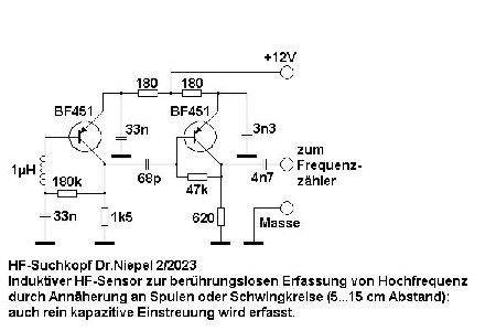
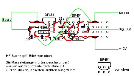
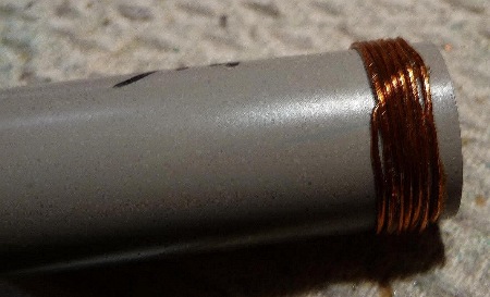
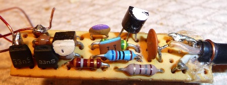 Die Spule ist links angelötet, die Kabel zum Oszilloskop bzw. Frequenzzähler und die Leitung für die Stromversorgung sind rechts zu erkennen.
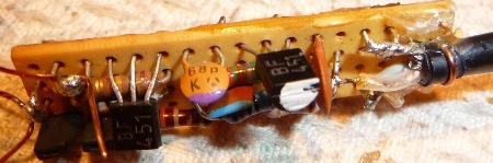
 Die Platine wird in das Plastik-Röhrchen geschoben, die Spule angeschlossen und das Ganze mit Schrumpf- schlauch umkleidet.
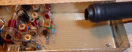 Noch aus einigen Zentimetern Abstand ist ein stabiles Signal zu empfangen.
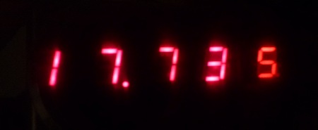 Stabile Anzeige des Frequenzzählers (17,735 MHz).
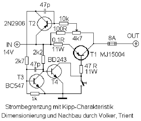 Schematics
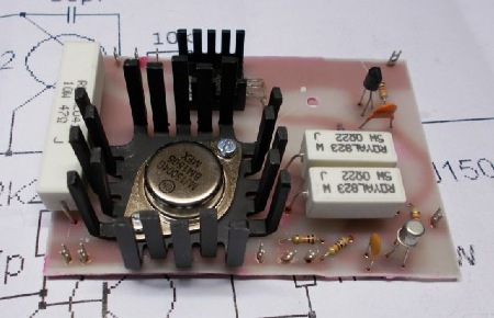 The board
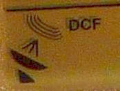 DCF-Symbol im Display eines Funkweckers
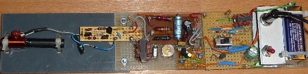 Empfänger zum Nachweis des DCF77 Signals. Ganz links: Antenne. Rechts: 9-Volt-Batterie.
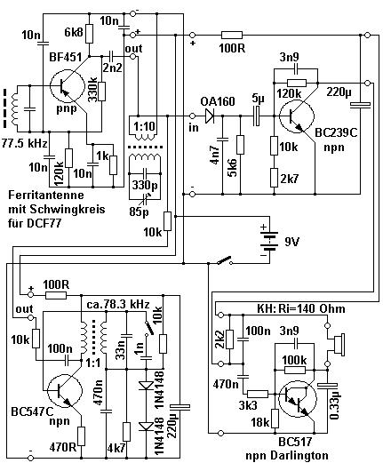 Schaltbild Empfänger für DCF77. Auf dem Download wesentlich besser zu sehen (siehe unten)! Please use the download for superior quality of graphic (below).
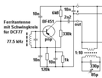 Teil (1) DCF77 Ferrit-Antenne. Sie ist als Schwingkreis für 77.5 kHz geschaltet. Rechts unten erkennt man den zweiten Schwingkreis für 77.5 kHz.
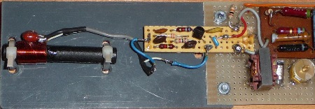 Ferritantenne und HF-Verstärker-platine. Rechts unten der zweite Schwingkreis. Darüber der Demodulator.
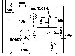 Teil (2) Schaltbild des BFO 78.3 kHz (lokaler Oszillator).
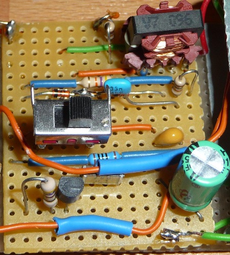 Lokaler Oszillator (BFO) für 78.3 kHz
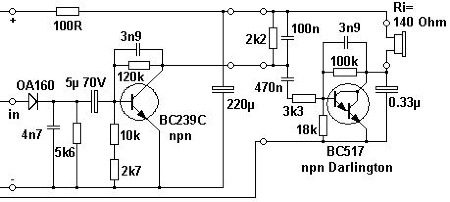 Teil (3) Demodulator und NF-Verstärker
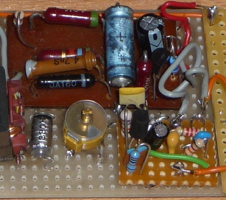 Demodulator und NF-Verstärker. Die erste Stufe ist auf der oberen Platine (wieder- verwertetes Material), die zweite Stufe auf der unteren.
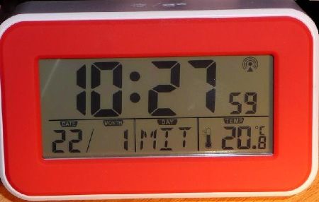 Kaum zu glauben, aber wahr: Dieser DCF77-Funkwecker erzeugt selber Funkstörungen bei 77.5 kHz und behindert damit seine eigene Funktion. Ein Wunder, dass er überhaupt funktioniert.
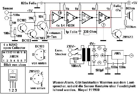 Das Schaltbild
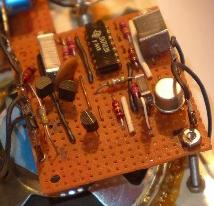 Vor 40 Jahren war das IC 7403N überall erhältlich. Heute könnten Sie es ersatzweise gegen ein 74LS03 austauschen. Höchstwahrscheinlich muss die Schaltung nicht einmal geändert werden.
 Die Platine mit dem Generator für den Sirenenton, dahinter der Lautsprecher.
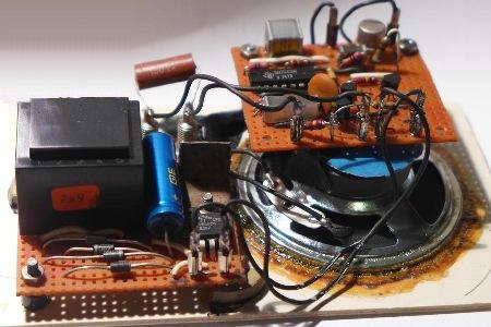 Vorne links das Netzteil mit dem Trafo (schwarz), dem Elektrolyt-kondensator (blau), den Gleichrichter-dioden und dem Spannungs-regler-IC. Vom Trafo verdeckt: Der zweipolige, beleuchtete Netzschalter.
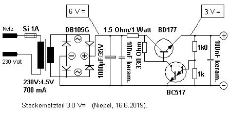 Stecker-Netzteil ohne Funk- störungen.
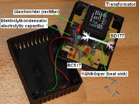
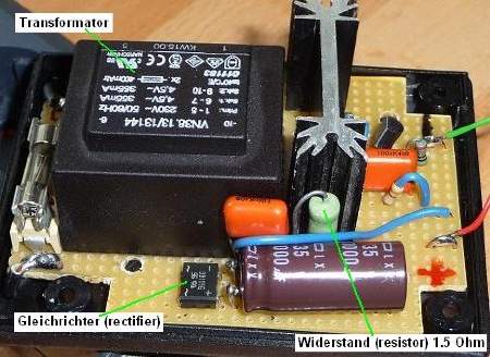 Seitenansicht der Platine
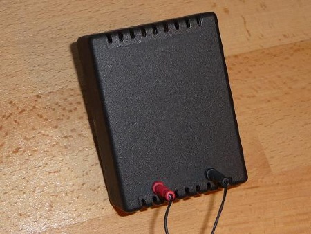 Anschlüsse am Ausgang
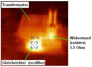 Thermografiebild:Seitenansicht der Platine während einer Belastung mit 180 mA. Keines der Bauteile wird nennenswert warm.
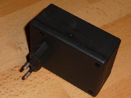 Steckernetzteil fertig zusammengebaut.
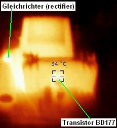 Thermografiebild des BD177: Er bleibt kühl bei 380 mA Belastung, denn er ist auf einem Kühlkörper montiert. Der Gleichrichter - ohne Kühlkörper - wird warm (55 Grad). Unmittelbar daneben, ebenfalls warm: Der Widerstand 1.5 Ohm.
 Comparison between indoor telescopic antenna (right image) and outdoor miniwhip antenna (left image). Both images were decoded from the same transmission of Shortwave Radiogram 146 (2020-04-04) on 15770 kHz. The image was transmitted by use of the digital mode MFSK64.
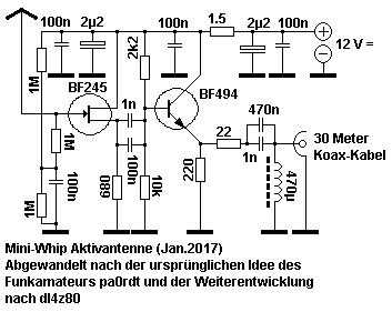 Danke an Herrn Walter, hier die korrigierte Version des Schaltbilds.
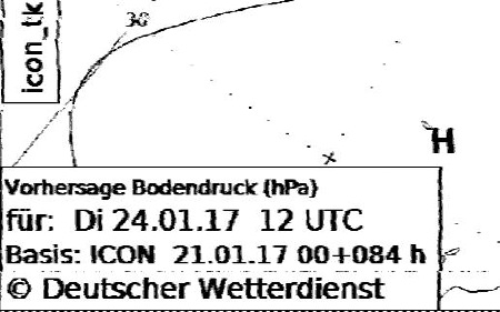 Dennoch haben wir in diesem Beispiel einen klaren Empfang der Wetterkarte auf 3885 kHz (HF-Fax). Das Bild zeigt einen Ausschnitt. Danke für die Genehmigung zur Wiedergabe an den DWD (Deutscher Wetterdienst).
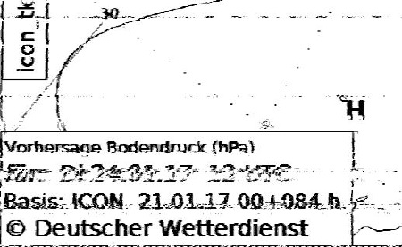 Mit der 10-Meter-Drahtantenne war der Empfang (selber Zeitpunkt, selbe Frequenz, baugleicher Empfänger) doch deutlich schlechter.
 Image decoded from Shortwave Radiogram using the miniwhip antenna.
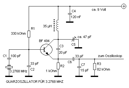
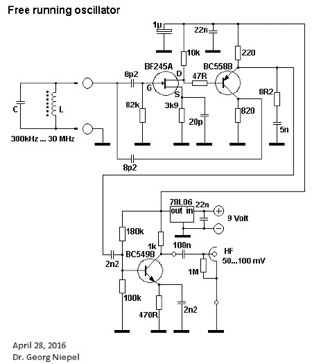
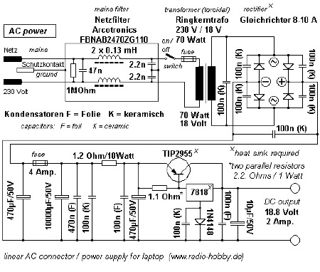
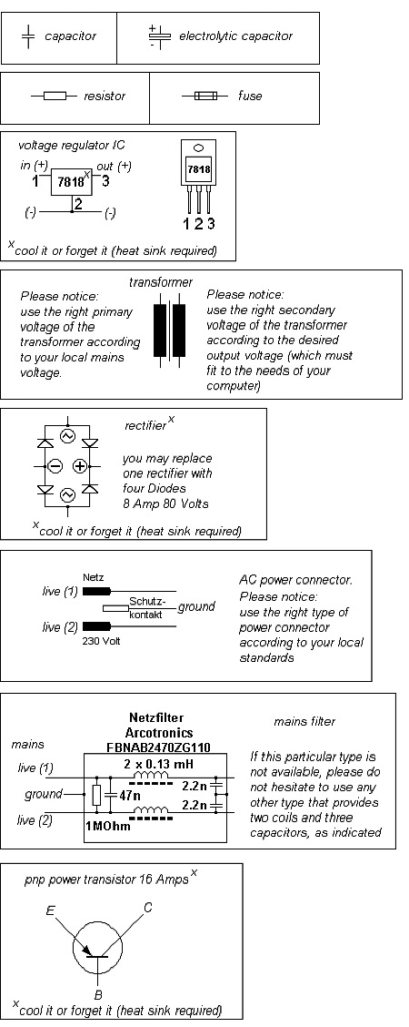
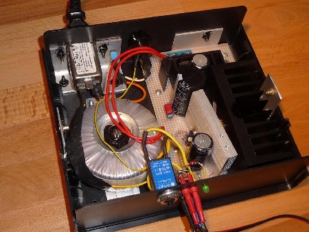
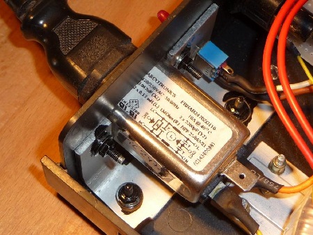 Netzfilter
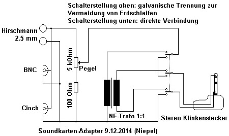
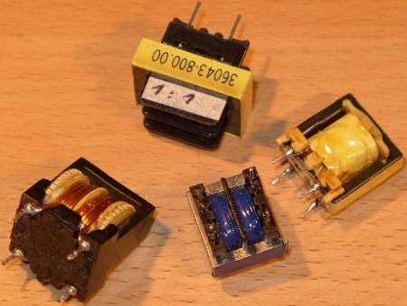 These audio transformers may be useful.
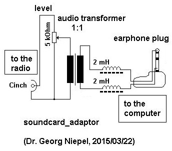 Simplified version of sound card adaptor.
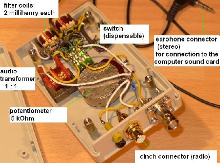 Here you may study one possible way to mount the sound card adaptor into a plastic box. Hier können Sie einen Vorschlag studieren, wie man den sound card adaptor in ein Gehäuse einbauen kann
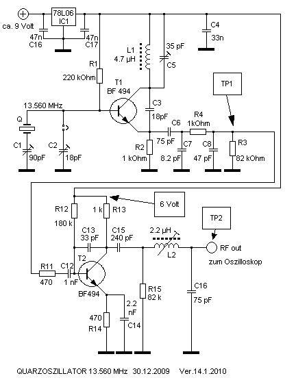
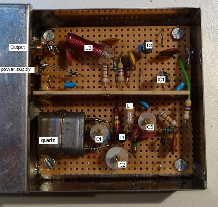
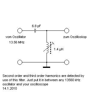
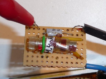
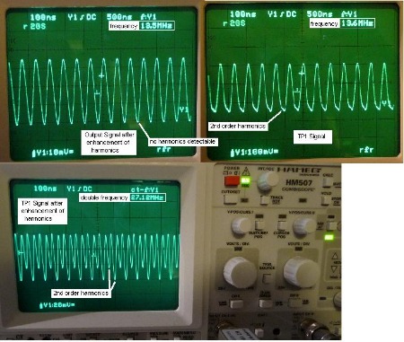
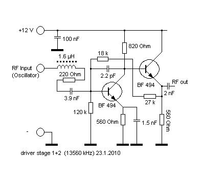
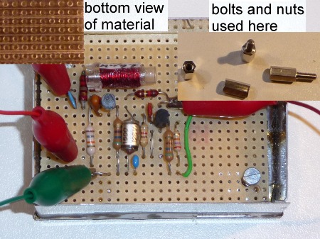
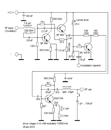
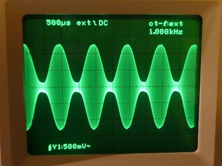
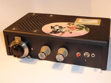
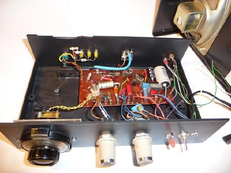
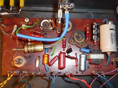
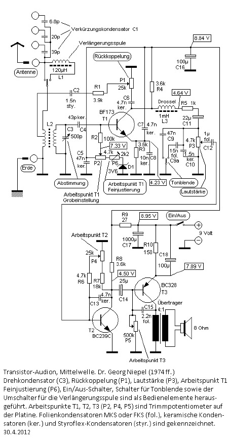 Antenne = antenna jack.
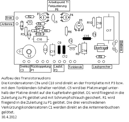
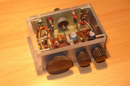
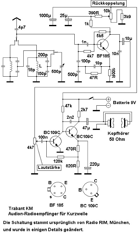
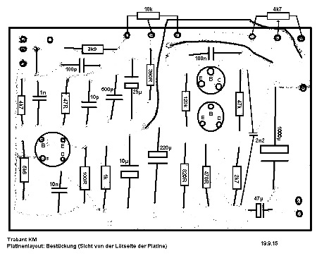
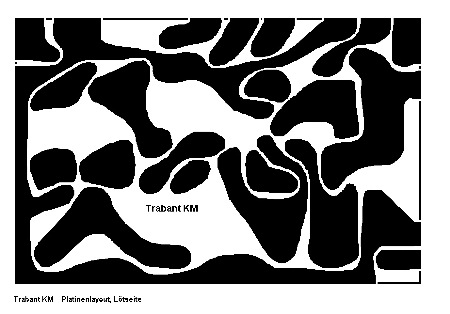
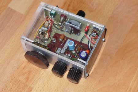 An der Rückwand findet sich eine "Kurz-wellenlupe", d.h. ein Dreh-kondensator mit sehr geringer Kapazitäts-varianz.
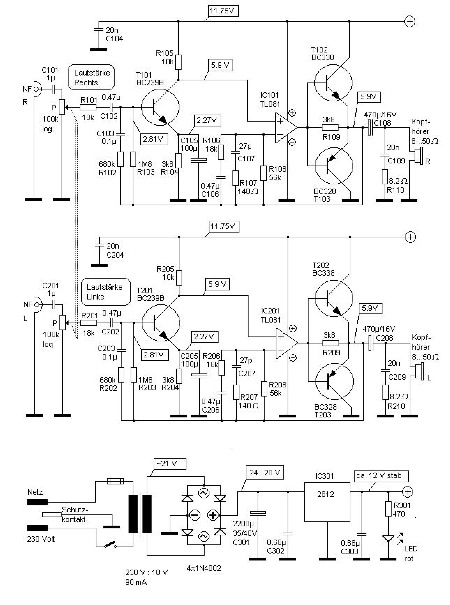
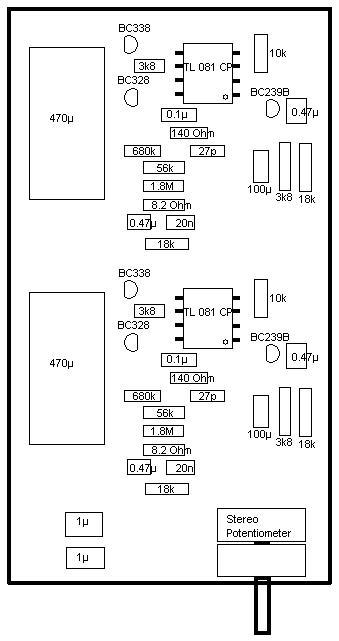 Proposal for the construction of the amplifier board.
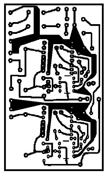 Amplifier board layout, bottom view: view on the copper / soldering side (designed May 1981) :
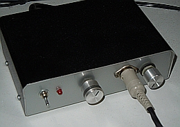
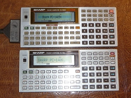 Sharp Pocket Computers PC-1401 and PC-1403H
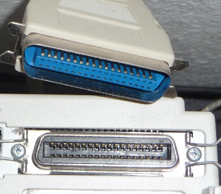 Centronics-Stecker und -Buchse an einem Epson-Nadeldrucker LQ300+
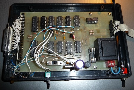 Der Aufbau des Centronics Interface für Sharp PC-1403H und Sharp PC-1401
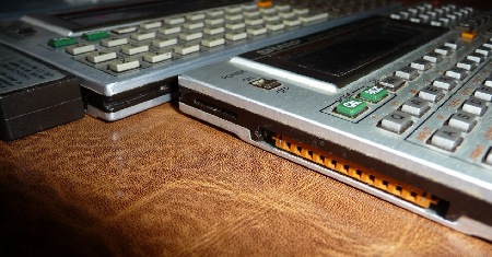 Der 11-Pin Steckanschluss am Sharp PC-1403H und Sharp PC-1401
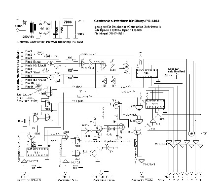 Schematics. Download by click on the symbol "JPG" to achieve a clear image.
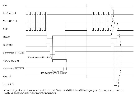 Signals as they appear inside the interface processing printing data (left) and supressing control bytes (right).
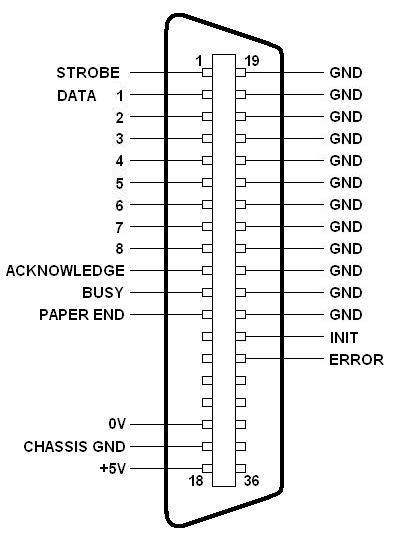 Centronics connector